
A thermal imaging camera with an Arduino UNO. Does it work? Yes it works!!
With this setup, you can quickly familiarise yourself with the function of an IR camera. Many applications in the field of temperature measurement are possible, e.g. recording the thermal conditions on an electronic assembly.
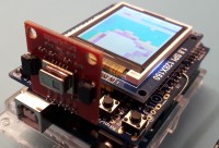
The key is a suitable sensor array. Panasonic's grideye sensor AMG88xx, with its 8x8 thermopiles, is the best choice for this. Unlike other sensors, the measured values are already processed internally and the valid data is made available via IIC. The array is housed in a solid metal casing that keeps the reference temperature stable for the duration of the measurement. It also has a lens that projects the object surface (measurement object) onto the sensor array.The measurement results are displayed on a 1.8" TFT for €5, either numerically or in false colours. The settings can be made manually or by autoranging.
The sketch contains the functions for the sensor directly, making it very easy to personalise the software for your own applications.
With this arrangement you can familiarize yourself very well with the function of an IR camera. Electronics engineers can record the thermal conditions on an assembly and much more is imaginable.
It is always fascinating to see what you can do with an 8-bit ATMEL.
Discussion (2 comments)