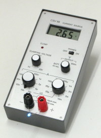
Adjustable DC current source with integrated hi-z DVM [130287-I]

With this portable instrument, you can safely test and measure very quickly all diodes, zeners, LEDs, etc... in their actual conditions of use, that is with a known and adjustable current, and up to a significant voltage (opposite to classic DVMs : unknown current, output limited to 3V or less).
With this portable instrument, you can safely test and measure very quickly all diodes, zeners, LEDs, etc... in their actual conditions of use, that is with a known and adjustable current, and up to a significant voltage (opposite to classic DVMs : unknown current, output limited to 3V or less). You can see the light efficiency from a LED, connect LEDs in series to make a visual selection, characterize a zener knee, estimate the leakage current of a diode with temperature, measure the avalanche voltage of a junction, measure very high resistances up to 2 gigaohms, and even capacitors with help of ... a stopwatch !
You can also disconnect the current source and use the instrument as a simple DVM with the particularity of a very high input impedance.
Main characteristics :
20 output current values from 10nA up to 20mA in 1-2-5 steps.
1.4% + 100pA output current precision
20V maximum output voltage.
Adjustable output clamping voltage from 1V up to 20V with LED indicator.
Integrated 3.5 digits two-range high impedance voltmeter.
0.2% voltmeter precision
4 x AA cells power supply.
110 hours battery life @ 1mA output


Discussion (5 comments)
patrickwie 10 years ago
JanB 11 years ago
Finished!
The finished project complete with fine Elektor-style schematics, a full description of its operation and adjustment appears in glorious color print in the April 2014 editons of Elektor magazine (except France).
Thanks Henri and Luc for engineering this one into publication.
Jan Buiting, Editor
sigo 10 years ago
Lucky 11 years ago
Lucky 11 years ago
Looks quite good, still some work to do, like wiring the rotary switches.
As expected there's always some tweaking to do on the PCB, some unexpected things like wrong dimensions in the datasheet of the LCD. The picture shows the display mounted on the PCB, after some bending of its pins. On top of it the same LCD in its original shape, this has to be corrected in the layout.
The fourth picture shows a silly mistake: the fixing nut of the potentiometer (almost) touches its pins and there's a trace + via underneath it. I overlooked that one :-(
The good news is that the voltmeter part appears to be working and most voltages on the test point look okay.
Time to finish the rotary switches, but first discuss with our photographer if he wants to takes pictures of this process.
130287-component-side.JPG (515kb)
lcd.JPG (101kb)
potmeter.JPG (87kb)
Lucky 11 years ago
henrip4 11 years ago
Lucky 11 years ago
Lucky 11 years ago
henrip4 11 years ago