

Air Ioniser [071072]
Allergic for grass pollen, trees, pollution, your cat, etc. This project, published in June 2009, might help you!
Negative is not always unhealthy
The amount of negative oxygen ions in the ambient air seems to affect the psychological and physical state of many people. The air in the mountains and near the sea contains relatively high numbers of negative ions compared to elsewhere and this is one of the reasons that you feel better in this type of environment. You can improve the air quality at home too, when using the ioniser described here.
There are two good reasons for ensuring that there are sufficient negative ions in the surrounding air. Firstly, ions are able to attach themselves to aerosols and dust particles. These then become heavier than the surrounding air and settle. Ions can also become attached to bacteria and germs, and make these harmless by electrically charging them. In this way the air is purified from dust and harmful organisms.
In addition, scientific research has shown that negative oxygen ions are essential for our metabolism. Breathing ionised air improves the oxygen concentration in the blood which results in better functioning organs and improved cell metabolism. These negative ions also seem to influence the production of serotonin in our body, a hormone that in the brain, among other things, influences the mood and self confidence in people. A greater amount of negative ions therefore ensures that you will feel better. Since the balance between the amount of positive and negative ions in the air at the office and at home is often upset, the addition of negative ions can positively influence both the air quality as well as the mood of the people present. This can be realised quite simply with the ioniser described here.
High voltage
What do we need to increase the amount of negative ions in the air? Not much, you only need a voltage which is sufficiently high so that the air at the point of a metal pin will be ionised. The oxygen ions produced this way easily spread through the air.To do this, we designed a small generator, which uses a converter followed by a cascade stage consisting of diodes and capacitors to generate a high voltage of 3.5 kV. The circuit uses standard components, it therefore contains no awkward transformer or other difficult to obtain parts. The component values are not all that critical either. You can certainly use a number of parts that you are likely to find in the bottom of your parts box.
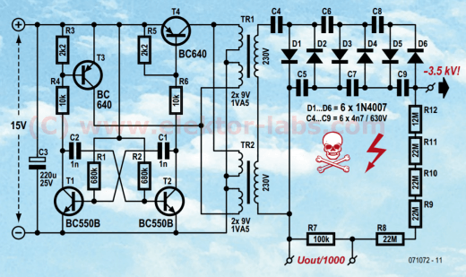
The schematic in Figure 1 shows the design. For the power supply we assume a DC voltage of about 15 V, obtained from a mains adapter. The oscillator that we use here is the classic astable multivibrator with two transistors (T1 and T2). The frequency is set with R1/R2 and C1/C2 to a little more than 1 kHz. Because of the two opposite-phase signals a mains transformer with two secondary windings is driven symmetrically. These secondary windings are actually used as the primary side here, so the transformer is used the ‘wrong way around’.
The relatively high self inductance of the transformer means that T1 and T2 cannot be used to drive the transformer directly. The astable multivibrator would generate irregular signals at the wrong frequency. To solve this two PNP-transistors (T3/T4) are added. These can switch more current and handle a higher voltage but are still housed in a TO-92 package (BC640, 80 V/1 A). R3 and R5 ensure that T3 and T4 do not turn on too early.
As you can see from the schematic, we are not using just one but two small transformers (small, short-circuit proof types, rated at 1.5 VA; you can use even smaller ones, for example 0.35 VA). The low-voltage windings (which are the primary side here) are connected in parallel, while the high-voltage windings are connected in series. In this way we immediately obtain twice the output voltage, compared to using only a single transformer. The consequence of this is that the cascade network can contain fewer diodes and capacitors (half as many in fact). The cascade, which consists of diodes D1 through D6 and capacitors C4 through C9, ensures that the peak output voltage is multiplied by six. At a power supply voltage of 15 V, the two transformers together generate a peak voltage of about 500 V, with ringing up to nearly 600 V. After the cascade multiplier the result is an output voltage of about 3.5 kV.
To be able to measure this voltage, a voltage divider is connected to the output, which consists of high-voltage resistors (type VR25 made by Vishay/BC-components, 1600 VDC). That means that R8 through to R12 are not ordinary resistors. Across R7 you can measure the output voltage divided by 1000 (or 1001 if you want to be exact). This voltage divider is not essential, but does enable you to check the actual output voltage. The input impedance of a even a 10 MΩ probe would already load the cascade way too much to allow the real output voltage to be measured accurately.

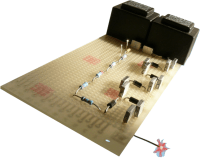
A needle with a sharp point is connected to the output. Here is where the ions are generated. It is also a good idea to connect a few high-voltage resistors between the output and the needle, so that the maximum current is reduced, should the needle be touched. The construction of the circuit is simple, which, even without a PCB, will be very little effort. If you are using prototyping board then make sure there is sufficient isolation distance between the primary and secondar y sides of the transformers and between the various steps of the cascade. If you have difficulty obtaining the prescribed capacitors of 630 V for the cascade then you can also use two 12 nF/400 V MKT in series instead.
Never touch the high voltage side when it is energised. Also wait a while after switching off to allow the capacitors time to discharge.
Once the circuit is working well it can be built into a suitable enclosure. Make a small hole in the case (5 mm diameter, for example) and mount the needle point behind this hole in such a way that you cannot touch the needle point when the enclosure is picked up.
Place the enclosure somewhere in your office or living room (not too close to large metal surfaces), connect it to a suitable mains adapter and let it do its job. After some time you will notice that the air appears not only cleaner and fresher but that you will also be in a better mood!
Discussion (4 comments)
RAUL RENDON 7 years ago
DRIVE BELTS FROM THE VCR.
dantop 7 years ago
Nice idea , but how not to make an ozon generator too ?(Ozon is not really good to breath...)
CopterCarl 7 years ago
I took some pictures of my electrode- system. The voltage measured at the end of the capacitor-ladder is ca. 3,6 kV (loaded by the resistor voltage divider). As you can see, the needles are mounted via 4,7 Meg as an array. So the current through the needles is equally distributed. The electrode gap is about 20 mm. You can see a round dark area on the “grid anode” (silver wire). This is an oxide film on the silver wire. I think there will be AG2_O and Ag2_S (Reaction with H2_S in the air).
For more information you can look at the links below:
https://de.wikipedia.org/wiki/Spitzenentladung
https://en.wikipedia.org/wiki/Corona_discharge
Warning: Do not use the red capacitors you can see in my pictures.
The value is too high, so the energy stored in it could be dangerous!!!
Take the value of 47 nF/600V.
Many greetings
Carl
Needles (1465kb)
Top (1783kb)
dantop 7 years ago
Thanks for your advises;
About electrodes , on the project only 1 is listed , and you talk about the distance of the electrodes meaning there are several ones ; could you give more details about ?
Thanks and highly voltage reagards
Dan
CopterCarl 7 years ago
I think that the generation of Ozon can't be avoided by the way, I built my
ion- grnarator.
But you have two possibilities to avoid a lot of ozon. You can set the intensity of the electrical field strength by changing the distance of the electrodes or/and changing the value of the high voltage.
My experience is to use not more than 3 kV.
The distance of the electrodes depends on the "quality" of the sharp needles.
Sharper elecrodes produce a higher field strength.
If you smell Ozon, it is to much and could be dangerous.
Many comercial ionizer are used for air cleaning.
The "Deutsche Lungenstiftung" warns against the use of Ionizer, which produce ozon, because the degrations products of nicotine and cigarette smoke is more dangerous!
Ozon is a strong oxidizing agents.
Best Regards
Carl
CopterCarl 7 years ago
I read about 40 years ago an article about a Receiver from Neckermann, who had built in an
Ion- generator(see attachment). That remained in memory.
http://www.radiomuseum.org/r/korting_neckermann_bio_ionisator_826235_koerting_36342.html
Three month ago I found a handful 1N 4007 Diodes and some capacitors and I started to build an “Ion-Generator”, what I always want to do.
The result you can see on the pictures.
For my Air Ionizer I used 2 transformers(230 V/ 16 V à 12 V/ 230V) instead of an electronic generator like Hedwig did (see circuit diagram) to isolate from main. The voltage at the 230 winding of the second trafo was about 240 V AC. I was surprised that the trafos got a little bit warm and so I measured the current between the two secondary windings. I measure an AC current of ca. 500 mA !
This current will flow through the real part of the coils (ohmic resistor) by a phase shift (see pictures).
It can be seen, that the current is seriously deformed by iron losses.
I use medical sharp needles(great electric field strength)as a cathode and a grid of silver wire for the anode.
To see, that a current is “flowing” through the air, I put a high efficient LED into the circuit.
I measured a DC current of about 2 uA and a HV voltage of ca. 3.1 kV.
If the field strength is too high, you can notice an unpleasant smells of Ozone! We have to avoid this, because O3 is harmful to health.
If you put your hand behind the wire grid you can feel a light breeze of air having a pleasant and fresh smell.
Do take care of the High Voltage (better to put one hand in your pocket ;)).
I sealed the breadboard, capacitors and diodes with plastic spray.
I did destroyed my old Metrawatt MH 1A multimeter (2 resistor, 4 diodes and a poti burned through) but it was interesting to open and repair it, because old fashioned instruments often are well documented J
I can’t measure the ions directly. I only can measure a current through the air.
I think there will be generated CO3-, NO3-, HSO4- Ions and O3 (Ozone).
Perhaps somebody knows more about the physics?
Furthermore I can say that I don’t feel better or bad, when I’m present near my generator.
I’ll keep running the ionizer for a while.
Have a nice time,
Carl
https://www.psiram.com/de/index.php/Luftionisation
ionizer2.jpg (737kb)
ionizer-led.jpg (1109kb)
20170619-172139.jpg (852kb)
20170619-172251.jpg (1343kb)
Kleinionen in der Luft (110kb)
Negative Ionen (33kb)
Circuit Diagram (107kb)
CopterCarl 7 years ago
thank you for your positive feedback.
Today I did a little experiment with a neon lamp.
I already knew what would happen: "nothing"(q.e.d).
You only have a static electrical field, without any changes in time(d/dt).
it's like a loaded capacitor and some ions are accelerated by a force(F=E x q).
There is no way, to bring any energy into the isolated(glass) neon lamp in order to lighten it.
You don't have a "Tesla- Generator".
Here a nice video on youtube of an Ionizer:
https://www.youtube.com/watch?v=DnpmqRRQ9ms
Carl
RONALD WAGNER 7 years ago
Have you ever tried to put a neon lamp in the path between the needles and grid? I wonder if the lamp would light up.
For your LED behind the grid, it looks like you have one side of the LED wired to ground and the other side attached just to the grid. Is that correct?
Ron
RONALD WAGNER 7 years ago