

Back ultrasound radar for bike:
Alert a city biker when some cars are approaching too close on the left side or on the right side.
For almost one year now, I m going to office by bike, crossing a crazy busy city by bus&cars (Shenzhen, China). When I was young and going to school by bike also, I was used to have small miror on left and right to see any cars overtake me on left or right.
Now, it is difficult to find this and I was thinking to a system, to alert me without loosing my view in front. The natural idea is to use US sensor, capable to give distance from 20cm to 4m.
As the plan is to be low consumption and solar power, I didn t want to use 5V or 3.3v regulator. One US sensor can accept large voltage input, with temperature compensation, US100 or Y401. They are capable of send the data from Rx/Tx or with a signal lengh. this second option will be use here.
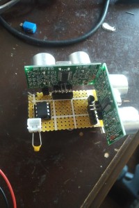
So far, I use a uC from Microchip, 12F1512 due to Fix voltage Reference inside, small (8 pins).
2 US sensors, position at 90 degres, will be trigger by the uC. the output goes to the Timer1 gate which count the distance. A simple rule to estimate the distance: duration in us * 34 / 200. this is given the distance in cm.
Then, how to give the alert to the rider ? That's the funny idea. I'm using 2 vibrators (from old mobile phone), put under the seat post of the bike, one on left and one on the right. The number of vibration will indicate if a car is close or far. 3 vibrations means close, 2 medium, 1 far but approaching.
Prototype is finished, code in C with MikroC (free version) as usual. Testing soon.
Laurent
Now, it is difficult to find this and I was thinking to a system, to alert me without loosing my view in front. The natural idea is to use US sensor, capable to give distance from 20cm to 4m.
As the plan is to be low consumption and solar power, I didn t want to use 5V or 3.3v regulator. One US sensor can accept large voltage input, with temperature compensation, US100 or Y401. They are capable of send the data from Rx/Tx or with a signal lengh. this second option will be use here.
So far, I use a uC from Microchip, 12F1512 due to Fix voltage Reference inside, small (8 pins).
2 US sensors, position at 90 degres, will be trigger by the uC. the output goes to the Timer1 gate which count the distance. A simple rule to estimate the distance: duration in us * 34 / 200. this is given the distance in cm.
Then, how to give the alert to the rider ? That's the funny idea. I'm using 2 vibrators (from old mobile phone), put under the seat post of the bike, one on left and one on the right. The number of vibration will indicate if a car is close or far. 3 vibrations means close, 2 medium, 1 far but approaching.
Prototype is finished, code in C with MikroC (free version) as usual. Testing soon.
Laurent
Discussion (1 comment)
HaSch 5 years ago
Although I made a lot of effort while setting up, unfortunately this did not work as it was intended. I have realized the project with 3 ultrasonic sensors and soldered everything clean on a breadboard (should finally look well on the bike ;-)
Motor 2 vibrates when approaching US2, both motors vibrate when approaching US3, but when approaching US1, neither motor vibrates. I checked the setup carefully and did not find any mistakes.
A test with the oscilloscope showed that impulses on TRIG2 and TRIG3 are well, but not at TRIG1. Since I suspected a defect of US1, I soldered it off again and looked at TRIG1 again. Still nothing. Meanwhile, I assumed a defect of the PIC and programmed a new one with the downloaded HEX file with the same result.
To exclude a wiring error finally, I took a third (fresh) PIC and also flashed it with the HEX file. Then I plugged it to a breadboard without further wiring and looked at the levels at the three outputs using the oscilloscope: At Pin2 and Pin5 everything looked fine, but at Pin6 was a constant potential of about 3.7V (voltage of Li -Po cell).
What's going on there? Is this a bug in the software? I looked into the source code and saw that TRG1 pin is shared with the RX1 pin, which may cause conflicts (see the comment about that in the source code). Therefore UART1 seems to be switched off but it doesn't work, thus. I compiled the software again to be sure the HEX file is corresponding with the source code but the result is the same.
HaSch 5 years ago
a first test said it's ok, it seems to work. I will do more tests if I have more time.
Thank you very much
Hans
gfaman 5 years ago
I looked the code and yes, there is a problem.
In case of 3 detectors, I forgot the line to send the distance to the vibrators.
Please find the code corrected, and the .HEX compiled with the 3 detectors and the correction.
These files are only for 3 US sensors !
Let me know if it is ok now,
Laurent
gfaman 5 years ago
The TRACE_UARTx define are for output some info to the serial link but it is in conflict with the vibrators, so it must not be use and keep at 0.
Laurent
HaSch 5 years ago
I did another test: I compiled the original source and compared the result with the .hex file you provided. Result: they are different!
The .hex file you provided does the job it has to do: with 2 sensors. The new compiled .hex does nothing!
You have to look after the source file, urgently. You have not to test it with 3 sensors, that what I will do. But I first have to get a source that will work with 3 sensors. Please look into the lines above and tell me what is wrong.
Thank you in advance and best regards,
Hans
HaSch 5 years ago
I looked into the code but I didn't understand completely: Have I to set the first line to because I use 3 sensors or have I to set to
What about the other lines? Are they right using 3 sensors? Have I to change other lines?
Regards,
Hans
HaSch 5 years ago
gfaman 5 years ago
Let me some times to check what's going on. Maybe a bug in the SW.
Did you recompile the Sw with the 3 sensors as the original Sw was with 2 sensors only ?
Anyway I will check.
Laurent