

Article
Big Amps DC Motor Driver
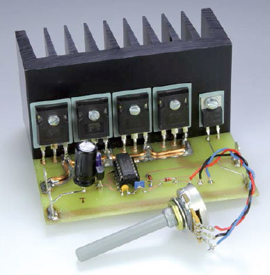
This simple circuit is designed for use with all kinds of DC motors up to 40 amps. Basically it’s just a simple oscillator driving a bunch of power MOSFETs, but it works a treat.
Materials
Gerber file
CAM/CAD data for the PCB referred to in this article is available as a Gerber file. Elektor GREEN and GOLD members can exclusively download these files for free as part of their membership. Gerber files allow a PCB to be produced on an appropriate device available locally, or through an online PCB manufacturing service.
Elektor recommends the Elektor PCB Service service from its business partner Eurocircuits or AISLER as the best services for its own prototypes and volume production.
The use of our Gerber files is provided under a modified Creative Commons license. Creative Commons offers authors, scientists, educators and other creatives the freedom to handle their copyright in a more free way without losing their ownership.
PCB
Component list
COMPONENT LIST
Resistors
R1 = 10kOhm, 5%, 0.25W
P1 = 100kOhm, 20%, linear potentiometer, 0.2W
Capacitors
C1 = 470µF 35V, 20%, 3.5mm lead spacing
C2 = 10µF 25V, 20%, 2mm lead spacing
C3 = 100nF, 50V, 20%, ceramic, 5mm lead spacing
C4 = 22nF, 100V, 20%, ceramic, 5mm lead spacing
Semiconductors
D1,D2 = 1N4148
D3 = RURP8100
T1-T4 = IRFP150N
IC1 = 40106
IC2 = 78L12
Miscellaneous
4 pcs. FastOn spade terminal (tab), straight, PCB mount, 0.2''(5.1mm) lead spacing
Heatsink, 1.9K/W, 100 x 40 x 50 mm, Fischer Elektronik type SK 92/50 SA
TO-3P silicone elastomer insulation (T1-T4)
TO-220 device insulating kit; mica sheet + bush (D3)
PCB # 120406-1 v1.0
Discussion (0 comments)
Quenton 6 years ago
Quenton 6 years ago
TonGiesberts 6 years ago
JLM7174 3 years ago
Jose Silveira 3 years ago
TonGiesberts 3 years ago
F1Andy 3 years ago
But surely you have no current limit, just a diode drop? Shouldn't there be a small resistance between the wiper of the potentiometer and the output of IC1a, to protect it?
I think the four Mosfets in parallel will load share better with individual gate resistors, and low value load balancing source resistors.
Is parallel connection of three outputs of the 40106 a good idea? Doesn't that assume all three outputs switch identically and no current circulates from one output into another.
It obviously works well enough as it is, but perhaps will suffer from reliability issues in the long term?
Just my 2 cents!
A.
TonGiesberts 3 years ago
The output of a 40106 inverter from the 4000 logic series has a fairly high output impedance and an extra gate resistor won't do much, except slowing down switching of the MOSFETs, The properties of the individual inverters from the same IC are not that different to worry about current flowing from one output to an other, At this low switching frequency of 1 kHz it's really not an issue. Furthermore the outputs are reasonably short circuit proof.
Any electronic circuit will fail at one point or another eventually.
F1Andy 3 years ago
Of course the output of the 40106 has its own internal output impedance, That's what I missed!
That makes my reliability comment not valid.
Thank you
Andy