Want to conduct experiments and tests on a CAN bus? You can with this DIY CAN tester design from 2013, which also offers the option of connecting an existing CAN bus to monitor the data or to track down faults.
Want to conduct experiments and tests on a CAN bus? You can with this DIY CAN tester design from 2013, which also offers the option of connecting an existing CAN bus to monitor the data or to track down faults.
CAN Tester Circuit
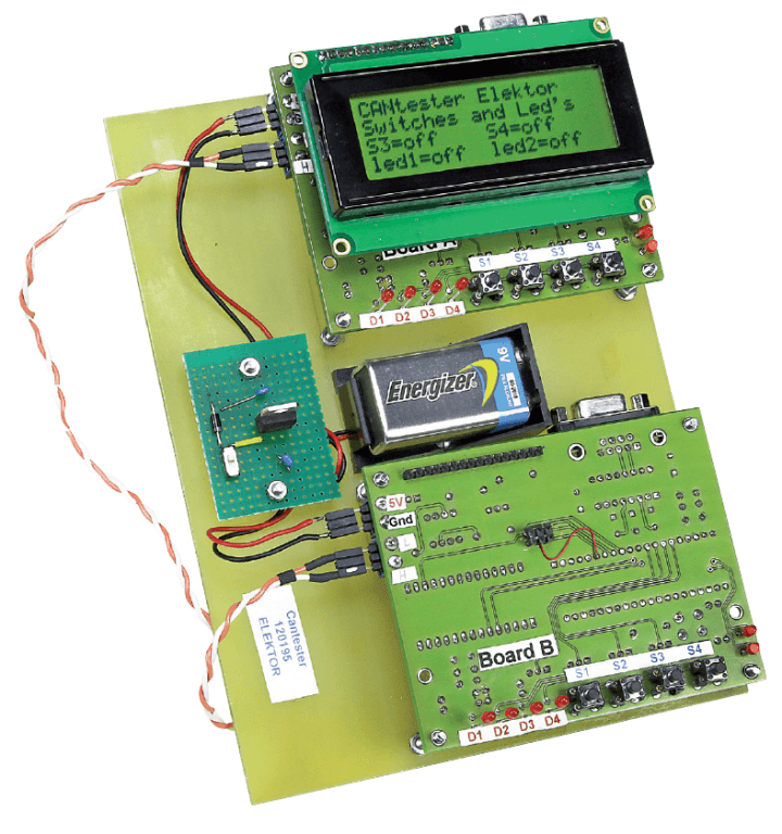
The CAN Tester design features two identical circuit boards (board A and board B), which are loaded with different software. You can equip each board with a 4 × 20 LCD. The boards communicate with in accordance with the CAN protocol, and they can also be connected to an existing CAN bus.
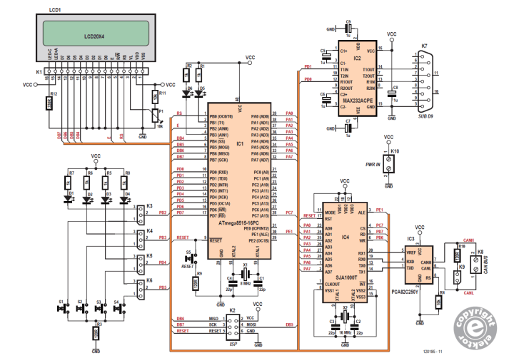
Figure 1. Schematic for the CAN Tester. The main ingredients are an MCU, a CAN protocol controller and a CAN transceiver
The circuit consists of several key components:
An ATmega8515 8-bit microcontroller (IC1)
An SJA1000 CAN protocol controller (IC4)
A PCA82C250 CAN transceiver (IC3)
MAX232: RS-232 transceiver (IC2, for communication with the PC)
A 4 × 20 character LCD (LCD1)
Subscribe
Tag alert: Subscribe to the tag DIY electronics and you will receive an e-mail as soon as a new item about it is published on our website!
"The SJA1000 is a bitstream processor with a transmit and receive buffer," Hugo Stiers explained. "This is controlled and initialized by the ATmega8515. The ATmega8515 provides the transmit buffer of the SJA1000 with messages and reads out the receive buffer. The SJA1000 is connected to the ATmega8515 via a multiplexed address/data bus (PA0 – PA7). In addition, there are four control signals that go to the SJA1000: CS (chip select), ALE (address latch enable), RD (read) and WR (write)."
Once constructed, the CAN Tester offers the following:
Test configuration with boards A and B, for 29-bit and/or 11-bit IDs (automatic)
Reading out of CAN data on the LCD (for example parking brake, odometer reading, etc.)
Reading out of CAN data on the LCD (for Examine data using HyperTerminal
Test functionality with pushbuttons and LEDs
Simulation of messages
Subscribe
Tag alert: Subscribe to the tag Circuits & Circuit Design and you will receive an e-mail as soon as a new item about it is published on our website!
Applications
In the article, Stiers describes a few different applications.
Application 1: Board A and board B send and receive messages automatically to each other
Application 2: Single CAN Tester with LCD (handbrake, odometer reading, etc.)
Application 3: Viewing data using Hyper-Terminal (baud rate = 57,600)
Application 4: CAN Tester with pushbuttons and LEDs
Application 5: The CAN Tester as a simulator for messages
The CAN Tester and More
Hugo Stiers's article, "CAN Tester with Comprehensive Features" appeared in Elektor November 2013, which Elektor Members can download immediately. Member benefits include: a subscription to ElektorMag, a 10% Elektor Store discount on many products, and full access to our online library. If you would like an Elektor membership, sign up today.
Editor's Note: This article was originally published in a previous edition of Elektor. Some of the products or PCBs may no longer be available in our store or elsewhere. However, we think the educational content remains valuable and hope it inspires you to embark on new and exciting projects.
Subscribe
Tag alert: Subscribe to the tag Test & Measurement and you will receive an e-mail as soon as a new item about it is published on our website!
Read full article
Hide full article
Add a rating to this article
★★★★★
★★★★★
Page 1 / 1
Login
No account yet?Register for free!
Forgot password?
Please enter your email address. Instructions for resetting the password will be emailed to you now.


Discussion (1 comment)
Werner-L 8 months ago
As the professional Vector VN1640A interface box offers the possibility to use different so-called "Piggies" to adapt to several data bus types, I would suggest to transfer the bus-specific interface chip and accessories to an interchangeable daughter board as well and enhance the software to handle both protocols.