Want a way to detect changes in the magnetic field? Check out this interesting do-it-yourself magnetometer circuit from 2007. The project was designed to detect even the smallest changes in field strength.
Want a way to detect changes in the magnetic field? Check out this interesting magnetometer circuit from 2007. The project was designed to detect even the smallest changes in field strength.
Variation Detection
There are essentially two types of magnetometers: those that measure the absolute value of the magnetic field strength and those that detect changes in the field strength. As Thomas Scarborough explained, this circuit was designed to detect variations.
“When this circuit was first designed, the author wanted to create a seismometer that was inexpensive and could operate in a stand-alone fashion (i.e., without the use of a PC or data logger). This resulted in a fairly simple circuit that used standard components, including a mains transformer as sensor and an LED bar graph as indicator. There is also a trigger (alarm) output that turns on when the full scale of the LED bar graph is reached.”
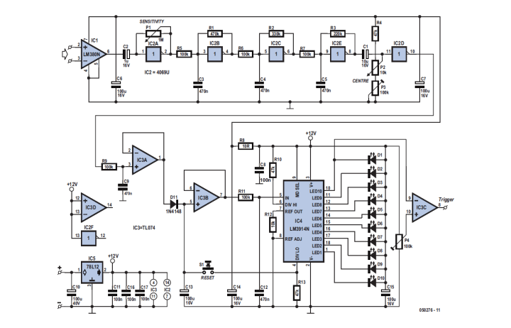
The diagram shows the many amplification stages. They ensure that even the smallest variations in the magnetic field can be detected.
The key part of the magnetometer is the detection coil. In the prototype, the author used a mains transformer (230 V/12 V, 2 A), but in theory, nearly any transformer or coil could be used. He also found that the model worked well and gave the circuit excellent sensitivity. The transformer's primary and secondary windings were connected in series (and in phase) to increase the sensitivity.
Subscribe
Tag alert: Subscribe to the tag Circuits & Circuit Design and you will receive an e-mail as soon as a new item about it is published on our website!
The coil was connected to the inputs of an op-amp (LM380). It was really a power-amp IC that could deliver 2.5 W, but it turned out to be just right for this circuit because it had a fixed gain (50 times) and the output automatically settled to half the supply voltage without the need for separate bias resistors at the inputs.
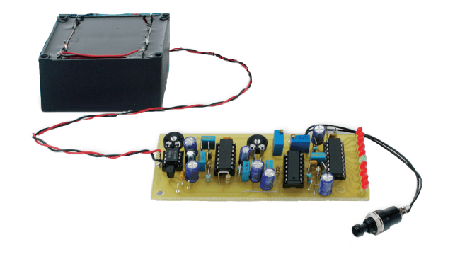
A PCB has been designed for the circuit to make the construction easier.
The low-frequency signal was then amplified further with gates from an unbuffered 4069UB CMOS IC. The author explained that an unbuffered CMOS inverter could be made to function as an amplifier with the addition of a resistor between the input and output. In this case, four inverters were used as sequential amplifier stages (IC2A/B/C/E) with passive RC low-pass filters in between (R5/C3, R6/C4, R7/C5). This provided a notable gain to the output signal from the LM380. All the filter stages (another two follow) reduced frequencies above about 20 Hz, mainly to suppress interference from mains-borne signals.
IC2D added another dose of gain to the signal, where the DC offset to the input of the gate was provided by potential divider R4/P2/P3. After another RC filter (R9/C9) the signal was buffered by IC3A and fed to a half-wave peak rectifier (D11/C13), which supplied a DC voltage to the input of the LED bar graph circuit.
The prototype used an old PCB-mounted transformer with all windings connected in series.
Magnetometer Projects and More
Thomas Scarborough’s interesting article, "Magnetometer: Detects Even the Smallest Changes,” appeared in Elektor May 2007, which is available to all Elektor Members. Members have several benefits: a subscription to ElektorMag, a 10% Elektor Store discount on many products, and full access to the online library. Don’t have an Elektor membership? Register today to start reading about past and present DIY electronics circuits and to access helpful engineering solutions.
Editor's Note: This article was published in a previous edition of our ElektorMag. Some of the products and/or PCBs mentioned may not be available in our store or elsewhere. However, the educational content remains valuable, and we hope it inspires you to embark on new and exciting projects.
Subscribe
Tag alert: Subscribe to the tag DIY electronics and you will receive an e-mail as soon as a new item about it is published on our website!
Read full article
Hide full article
Add a rating to this article
★★★★★
★★★★★
Page 1 / 1
Login
No account yet?Register for free!
Forgot password?
Please enter your email address. Instructions for resetting the password will be emailed to you now.


Discussion (1 comment)