Build your own budget-friendly resonance meter, a versatile RF test instrument capable of measuring frequencies from 100 kHz to 50 MHz. Originally introduced in 1989, this DIY tool also functions as a capacitance meter, RF test generator, and signal probe.
Build your own budget-friendly resonance meter, a versatile RF test instrument capable of measuring frequencies from 100 kHz to 50 MHz. Originally introduced in 1989, this DIY tool also functions as a capacitance meter, RF test generator, and signal probe.
Project Overview
This interesting RF test instrument was first designed in 1989 — you know, back when George H.W. Bush was the US president, Helmut Kohl was the German Chancellor, and engineers were talking about Intel's 80486 microprocessor! The budget-friendly resonance meter was presented as an invaluable tool for anyone working with radio frequency (RF) signals. Capable of measuring resonance frequencies from 100 kHz to about 50 MHz, the versatile device also functioned as a capacitance meter, RF test generator, and RF signal probe.
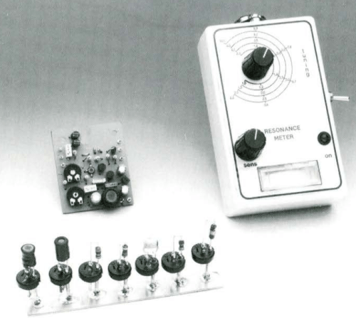
The resonance meter project.
Originally known as a "grid dipper" during the vacuum tube era, the instrument later became the "gate dipper" with the advent of semiconductors. The name change reflected the similarity between a field-effect transistor (FET) gate and a vacuum tube grid. However, to more accurately describe its purpose, the modern term "resonance meter" is now used. The resonance meter operates as an adjustable RF signal source, coupling to a circuit and measuring the amplitude of the output signal.
Subscribe
Tag alert: Subscribe to the tag Test & Measurement and you will receive an e-mail as soon as a new item about it is published on our website!
The Circuit
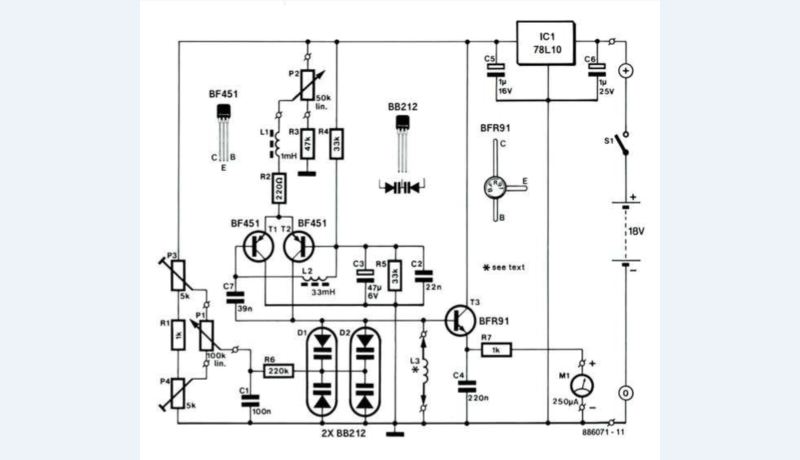
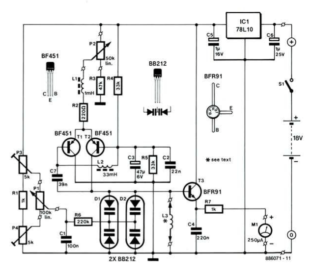
Refer to the circuit diagram of the resonance meter. All functions are realized by three transistors and a handful of passive components. T1 and T2 form an oscillator, the designer J. Bareford explained. The frequency of oscillation is determined by L3 and varicaps D1 and D2. The two diodes are connected in parallel to achieve the required capacitance range that can be adjusted with P1. A total of eight plug-in inductors is required to cover the frequency range from 0.1 to 50 MHz.
Circuit diagram of the budget resonance meter for 0.1 - 50 MHz in eight ranges.
"The resonance meter is a test instrument that becomes easy to operate only gradually through regular practical use," Bareford noted.
Before any measurement, the frequency range must be determined, and the appropriate pick-up coil selected.
"In some cases, you will need to change coils if the resonance frequency is close to the end of the range. Switch on the instrument, and adjust the sensitivity control, P2, for f.s.d. (full-scale deflection) of the signal level meter. Line up the pick-up coil with the inductor in the equipment, and tune carefully until the pointer of the level meter moves to the left. The frequency range is probably fairly large at this stage. To achieve a more accurate dip, move the pick-up coil away from the inductor while still ensuring that they point in the same direction."
Using the resonance meter to 'dip' an L-C tuned circuit.
Resonance Meter Project
The article, “Resonance Meter,” appeared in Elektor September 1989. You can read the article free during the two weeks following the publication of this post. When you start a project of your own, be sure to share your progress on the Elektor Labs platform!
Editor's Note: This article was first published in a 1989 edition of ElektorMag. Due to the project’s age, some of the components, PCBs, products, or links might not be available. Still, we think the content is an informative resource, and we think it will inspire you to begin new DIY electronics projects at your workbench.
Subscribe
Tag alert: Subscribe to the tag Circuits & Circuit Design and you will receive an e-mail as soon as a new item about it is published on our website!
Read full article
Hide full article
Add a rating to this article
★★★★★
★★★★★
Page 1 / 1
Login
No account yet?Register for free!
Forgot password?
Please enter your email address. Instructions for resetting the password will be emailed to you now.


Discussion (0 comments)