The "USB Magic Eye" circuit was presented back in 2010 as a handy CPU meter with a retro look. A USB port provided power and control, and a glowing value indicated CPU load. Let’s take a look at the design.
The "USB Magic Eye" circuit was presented back in 2010 as a handy CPU meter with a retro look. A USB port provided power and control, and a glowing value indicated CPU load. Let’s take a look at the design.
CPU Meter Circuit and PCB
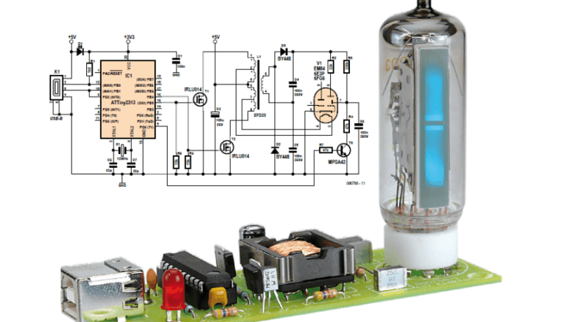
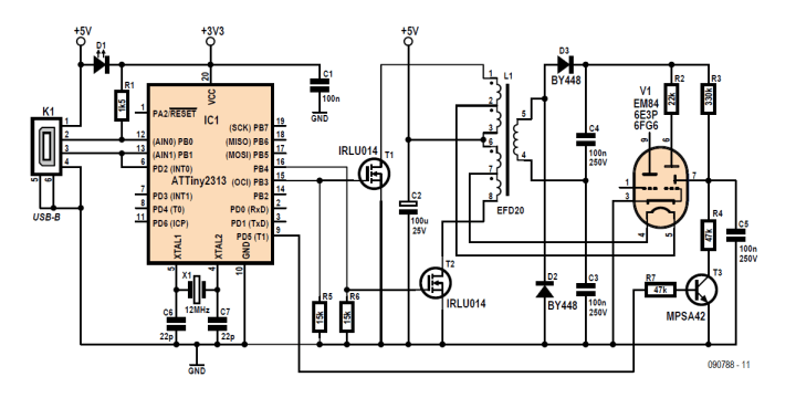
The EM84 valve requires a heater voltage of 6.3 V as well as an anode voltage of approximately 200 V. A compact unregulated, push-pull converter is used to generate these voltages from the 5 V supply provided by the USB port. The converter's output voltages are determined by the turns ratio of the transformer in the circuit.
Overview of the circuit
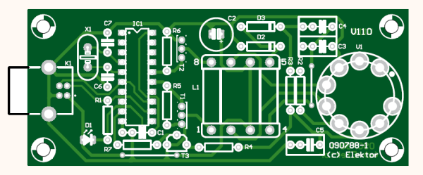
Refer to the nearby PCB for the EM84-based CPU meter, which was designed in the Elektor Lab. All components, including the valve base, were fitted to the board, the designer Martin Ossmann explained. "All the components are leaded and of course care must be taken to fit polarized devices the right way around: this applies to all diodes and transistors, the microcontroller (in a DIL package), the transformer, and electrolytic capacitor C2."
The PCB
The Program
Ossmann wrote the program in C to send the CPU load information to the AVR microcontroller.
"If the program is run without any parameters, it first gradually increases the switching supply duty cycle,” he explained. “Then, every tenth of a second, it determines the CPU load value and sends it to the AVR as a percentage. The PWM duty cycle needs to be controlled over a certain range for use with the magic eye version of the circuit, and this range can be specified by passing two parameters to the program. If just one parameter is given a fixed duty cycle is output. This allows for test and calibration: for example, to calibrate the 100% point, run the program as CPUshow 100 <return> and then adjust potentiometer P1 to obtain a full-scale deflection on the meter."
The Magic Eye Article
Ossman’s article, “USB Magic Eye: Valve indicates CPU load,” was published in Elektor January 2010. The article will be free to download by everyone in the community for at least the two weeks after the publication of this news item. Enjoy!
Editor's Note: This article was originally published in a previous edition of our magazine. Please note that some of the products (e.g., PCBs) and links may no longer be available. However, we believe the educational content remains valuable and hope it inspires you to embark on new and exciting projects.
Subscribe
Tag alert: Subscribe to the tag Circuits & Circuit Design and you will receive an e-mail as soon as a new item about it is published on our website!
Read full article
Hide full article
Add a rating to this article
★★★★★
★★★★★
Page 1 / 1
Login
No account yet?Register for free!
Forgot password?
Please enter your email address. Instructions for resetting the password will be emailed to you now.


Discussion (3 comments)