Want to repurpose an operational amplifier from a previous project or an old parts collection? You can construct a specialized op-amp tester quickly and inexpensively.
Want to repurpose an operational amplifier from a previous project or an old parts collection? Be careful: its functionality might be compromised. Testing an op-amp with a multimeter for a simple pass/fail result isn't as straightforward as it is for components like resistors, coils, fuses, diodes, or capacitors. You can construct a specialized tester for op-amps quickly and inexpensively.
Op-Amp Tester Circuit
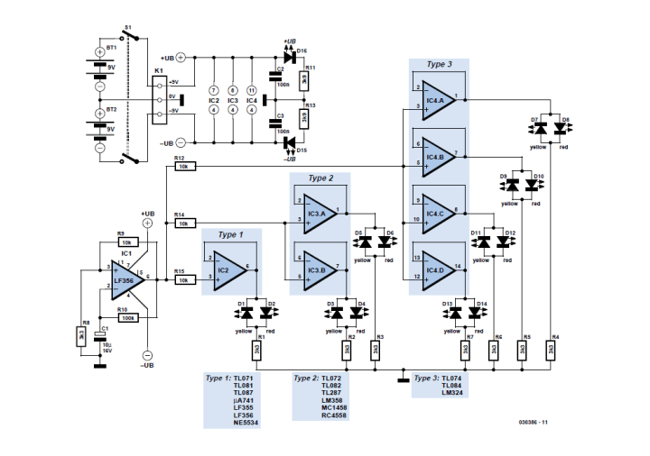
Refer to the test circuit, which consists of a simple squarewave oscillator (IC1) that oscillates with a frequency of approximately 1 Hz. As the designer, Dirk Schumacher, explains, the output of the oscillator (on pin 6) swings between “high”, +(Vb–0.5 V), and “low”, –(Vb–0.5 V), with a period of about 1 s.
Figure 1: The circuit can test single, dual and quad op-amps.
“The results of the test are displayed using low current LEDs. If the output of the op-amp is high, the red LED will light; if the output is low, the yellow LED will light. The op-amps under test will need to be able to sink and source a current of at least 2 mA,” Schumacher explains. “The test unit is powered from two 9 V PP3 (6F22) type batteries (BT1 and BT2). D15 and D16 indicate when the supply voltage is present on all the relevant pins of the oscillator and of all the test sockets.”
Quick go/no-go testing for operational amplifiers.
The design should be a handy addition to your electronics workbench.
The PCB
Extra info / Update
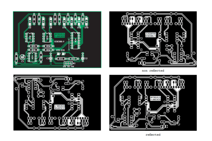
Unfortunately the printed circuit board for the above project contains a mistake concerning the supply voltage to the opamp in position IC4. However, the problem is easy to solve.
Using a sharp hobby knife, completely isolate pins 11 and 4 of IC4 from the rest of the circuit by cutting all copper tracks to these pins. On the IC socket, bend out pins 4 and 11 sideways and solder a short wire to each pin. Solder the IC socket in place (at the underside of the board). Connect the wire on socket pin 4 to the positive supply voltage. Connect the wire on socket pin 11 to the negative supply voltage.
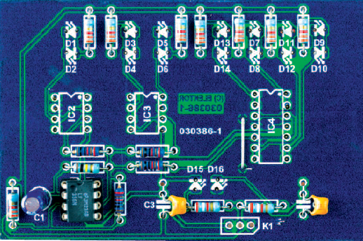
Populate the rest of the board as indicated by the component mounting plan.
Please note that sockets IC2, IC3, IC4 and LEDs D1 through D16 have to be fitted at the solder side (underside) of the board. This allows the board to be better mounted in a case.
More About the Tester
The article “Opamp Tester” appeared in Elektor 3/2005. Elektor Members have full access to Elektor’s library, which includes this informative article.
Subscribe
Tag alert: Subscribe to the tag Circuits & Circuit Design and you will receive an e-mail as soon as a new item about it is published on our website!
Read full article
Hide full article
Add a rating to this article
★★★★★
★★★★★
Page 1 / 1
Login
No account yet?Register for free!
Forgot password?
Please enter your email address. Instructions for resetting the password will be emailed to you now.


Discussion (2 comments)
J.F. Simon, Elektor 4 months ago
Unfortunately the error is present in the PCB too, so it's needed to correct the wiring. This shouldn’t be too difficult, as Pins 4 and 11 can be isolated from the tracks with an x-acto knife and connected correctly to the +9V plane and the -9V track with a few solder bridges. These power rails are close by.
Also, the Opamps Under Test are meant to be connected to DIP sockets that should be soldered on the back (copper) side of the PCB. This way the Elektor PCB can be mounted flush against a front panel that you may build for the tester, with the sockets accessible through holes in the panel. The LEDs are mounted on the back for the same reason. Good luck and happy opamp testing!
jarede2000 4 months ago