

Circuit: Revised Dynamic Limiter
August 30, 2024
on
on
Back in 2010, Elektor engineer Ton Giesberts presented a revised version of an audio limiter that was intended to limit the (possibly
excessive) dynamic range of the audio signal. The original circuit was designed to reduce an overly powerful source signal, whereas the revised approach focuses on boosting quieter sections. To reduce the usual 'breathing' effect associated with compressors, the control range is confined to 24 dB. The gain is modified in discrete, inaudible increments, preventing nonlinearity and, therefore, eliminating distortion.
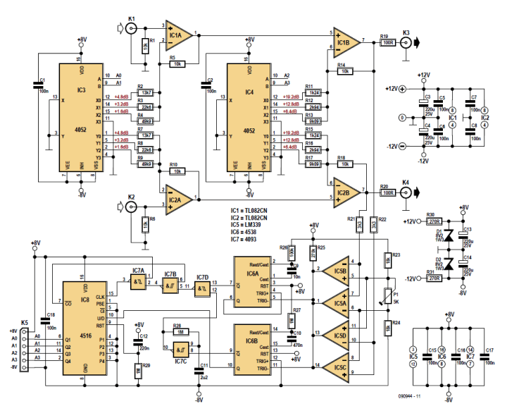
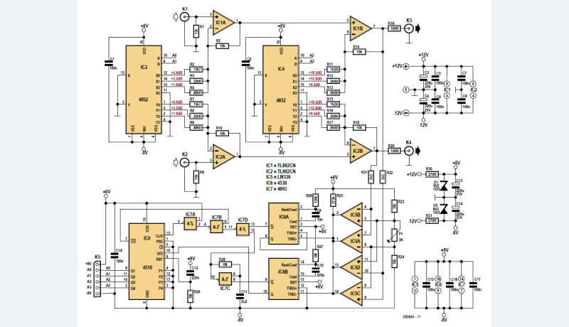
"The voltage divider used in the original circuit has been replaced here by negative feedback circuitry using two noninverting amplifiers. This reduces the number of resistors and allows smaller multiplexers to be used — in this case consisting of two halves of a 4052 IC per channel (the 4052 is a dual 1- of-4 analogue multiplexer/demultiplexer)."
The control circuitry is largely made up of simple discrete logic, he noted. "The multiplexers are driven by an up/down counter (IC8). Window comparators are used to determine the signal level at the output. They are built around two comparators of an LM399 (quad comparator) for each channel. The same reference voltage (across P1), at approximately 1 V, can be used for both channels. The reference voltage can be modified by changing the value of P1 — for instance, 10 kΩ yields around 1.7 V. The con trol circuit responds to the peak level of the output signal. As long as the output signal level is lower than the reference level, oscillator IC7c is enabled by monostable multivibrator IC6b. This causes IC8 to count down slowly (pen 10 of IC6 is low) until the lowest count is reached. The counter is then blocked by IC7b, and the gain is set to the maximum (the X0 outputs of IC3 and IC4 are at ground level). IC6b is triggered when the window comparators generate pulses. The outputs of IC6b remain asserted as long as this occurs (the 4528 is retriggerable), and oscillator IC7c is blocked. IC6a is now triggered by the comparators. The Q output of IC6a is connected to the positive trigger input to prevent retriggering of IC6a. In this situation, the counter is clocked by pulses from IC6a (pin 7)."
Editor's Note: This article was first published in a 2010 edition of Elektor magazine. Please note that some of the components, products (e.g., PCBs) and links may no longer be available. However, we believe the educational content remains valuable and hope it inspires you to start new projects.
excessive) dynamic range of the audio signal. The original circuit was designed to reduce an overly powerful source signal, whereas the revised approach focuses on boosting quieter sections. To reduce the usual 'breathing' effect associated with compressors, the control range is confined to 24 dB. The gain is modified in discrete, inaudible increments, preventing nonlinearity and, therefore, eliminating distortion.
The Schematic
With the component values noted in the schematic diagram, the circuit can boost the gain in 15 steps of 1.6 dB each, yielding 16 levels from 0 to 24 dB, Giesberts explained."The voltage divider used in the original circuit has been replaced here by negative feedback circuitry using two noninverting amplifiers. This reduces the number of resistors and allows smaller multiplexers to be used — in this case consisting of two halves of a 4052 IC per channel (the 4052 is a dual 1- of-4 analogue multiplexer/demultiplexer)."
The control circuitry is largely made up of simple discrete logic, he noted. "The multiplexers are driven by an up/down counter (IC8). Window comparators are used to determine the signal level at the output. They are built around two comparators of an LM399 (quad comparator) for each channel. The same reference voltage (across P1), at approximately 1 V, can be used for both channels. The reference voltage can be modified by changing the value of P1 — for instance, 10 kΩ yields around 1.7 V. The con trol circuit responds to the peak level of the output signal. As long as the output signal level is lower than the reference level, oscillator IC7c is enabled by monostable multivibrator IC6b. This causes IC8 to count down slowly (pen 10 of IC6 is low) until the lowest count is reached. The counter is then blocked by IC7b, and the gain is set to the maximum (the X0 outputs of IC3 and IC4 are at ground level). IC6b is triggered when the window comparators generate pulses. The outputs of IC6b remain asserted as long as this occurs (the 4528 is retriggerable), and oscillator IC7c is blocked. IC6a is now triggered by the comparators. The Q output of IC6a is connected to the positive trigger input to prevent retriggering of IC6a. In this situation, the counter is clocked by pulses from IC6a (pin 7)."
The Dynamic Limiter Article
The article, “Dynamic Limiter,” was published in Elektor July/August 2010. The article will be free to download for at least the two weeks after the publication of this news item. Enjoy the article!Editor's Note: This article was first published in a 2010 edition of Elektor magazine. Please note that some of the components, products (e.g., PCBs) and links may no longer be available. However, we believe the educational content remains valuable and hope it inspires you to start new projects.
Subscribe
Tag alert: Subscribe to the tag Circuits & Circuit Design and you will receive an e-mail as soon as a new item about it is published on our website! Read full article
Hide full article


Discussion (0 comments)