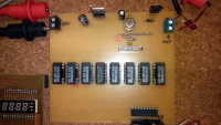
Digital control constant current source

Digital controlled current source with the good old 723H.
This project object is an digital controlled current source with standard parts, low cost and high stability. The analog circuit is inspired by Elektor 11/77, first test on breadboard looks very good. As load three LEDs in this example. The schematic and simulation is attached.
Project Elements
old_breadboard_test (JPG, 793.04 KB)
test on breadboard
20170525_bottom_view (JPG, 665.81 KB)
Bottom view, soldered PCB
Stand 06.05.2017 Schaltung (PNG, 102.71 KB)
Vorläufige Schaltung der Stromquelle
Simulation in LTspice
(ZIP)
Simulation der Konstantstromquelle in LTspice
Discussion (2 comments)

PPihkala 7 years ago
Why to use NPN (Q1, BD139) as control element, since it's base current will create an error at the output current? I think this should work at less current error with N-MOSFET at Q1. If needed for stability by IC1 just add extra load resistor from it's gate to ground (1-5k ?).
If power rating of single resistors is not enough, then use more in parallel, with bigger values of course.
I also find it odd that you have the value setting resistors at the power path, which makes you to use all these relays.
If power rating of single resistors is not enough, then use more in parallel, with bigger values of course.
I also find it odd that you have the value setting resistors at the power path, which makes you to use all these relays.
Reply

Bonkers 7 years ago
NFET is good.
I'm not sure the current error is only 1mA - the BD139 has a minimum gain of 40 at 150mA - so about 6-7mA error at 250mA out, in the worst case.
using 2N7002 NFETs would replace most of the relays - you would need a bigger MOSFET for the MSB, possibly for MSB-1 also, but it saves a lot of space and a lot of power supply capacity.
Reply

runni 7 years ago
Many Thanks guys,
you are right, I forgot the base current. The max. error is round about 1mA at max. current. In the original circuit from 1977 was this not an topic.
I change the BD139 to an N-FET it looks better.
I like the relays, is galvanic decoupled. Is only for hobby use, and I was surprised over the good stabilization from the 723 circuit. For test some LEDs or other parts with constant current is it enough.
The 2N7002 has max 5R on resistance, in worst case as relay replacemet at 250mA has an 40mA error!
LTspice Test mit N-FET (15kb)
Reply

PPihkala 7 years ago
The problem I see here is that collector current and measured (emitter current) of Q1 are not the same. Therefore if the hfe of the NPN is not constant at different currents, then there will be an error between set value (emitter current) and load (collector) current . With MOSFET the drain and source currents would be the same, because there is negligible gate-source current.
Reply
Show more
6 Comment(s)

ClemensValens 7 years ago
Wouldn't it have been easier (and cheaper) to use a digital potentiometer instead of all the relays?
Your schematic refers to the metal-can (H) version of the LM723?
I have problems running the simulation, LTSpice complains about the LED.
Your schematic refers to the metal-can (H) version of the LM723?
I have problems running the simulation, LTSpice complains about the LED.
Reply

F. Giam 7 years ago
Hello to all,
In my case, when i need a current source or sink, i use a classic current generator build with a good AOP and un classic BJT, or NMOS. A small pic to make a PWM signal with two low pass filter and of course a software feedback. On this design realise by one hundred students, we have a resolution around 2mA.
In my case, when i need a current source or sink, i use a classic current generator build with a good AOP and un classic BJT, or NMOS. A small pic to make a PWM signal with two low pass filter and of course a software feedback. On this design realise by one hundred students, we have a resolution around 2mA.
Design of a capacimeter (39kb)
Reply

Helmut Sennewald 7 years ago
Hello Clemens,
you could use the LED LXHL-BW02 from LTspiceXVII.
If you add n=3, LTspice assumes 3 LEDs in series.
LXHL-BW02 n=3
The schematic has used a BC337. It's only for simulation. It would not stand the power dissipation in this application. One should use a Darlington transistor with an appropriate heatsink in a real circuit.
Best regards,
Helmut
Reply

runni 7 years ago
Now high precision resistors are cheap, this why this circuit has an good stability and low error, an digital pot brings big problems in temperature and load stability.
I have an lot of metal-can (H) LM723 in storage, is also available in surplus, has an better stability.
The LED in LTSpice: you can use any kind of load, what you want.
I have an lot of metal-can (H) LM723 in storage, is also available in surplus, has an better stability.
The LED in LTSpice: you can use any kind of load, what you want.
Reply
Show more
3 Comment(s)


Updates from the author
runni 3 years ago
runni 3 years ago
http://www.auram.de/cms3/pages/elektronik/digital-gesteuerte-stromquelle-dcccs.php
runni 7 years ago
- The last working circuit version is LTspice_cs_nfet 6. Juni 2017, 21:48
- An update with new eagle files will come in few days
- The best values will reach the 100μA per step version, 100µA to 25,5mA
- The actual version 1mA - 255mA works ver well, between 1mA and 100mA, over 100mA the error is round about 5mA (depending on the resistors used and their TC)
- You can find an short hint on this project on Elektor Magazin Nr.557 September/Oktober 2017 :-)
- References to errors are welcome, this project is not intended for professional use. That one also easier to reach the goal is clear to me.
runni 7 years ago
Relais from german shop Pollin: No. 340 781 with 2 reed contacs
uA723H maybe from ebay round about 3€ or ask me.
Resistors from Digikey....
All other parts are quite normal.
runni 7 years ago
All curent measurment resistors 0805 0.1%.
Output 1....40mA with out heatsink.
PCB bottom (577kb)
40mA output test (1211kb)
runni 7 years ago
I think for 0805 resistors is from 0 to 25mA in 100uA steps better, for more power, use bigger resistors.