Elektor Lab Notes 20: Sensor Evaluation Board, Test Equipment and More
on
Saad Imtiaz (Senior Engineer, Elektor)
Lab Notes: Sensor Evaluation Board and AmpVolt 2.0
Sensor Evaluation Board
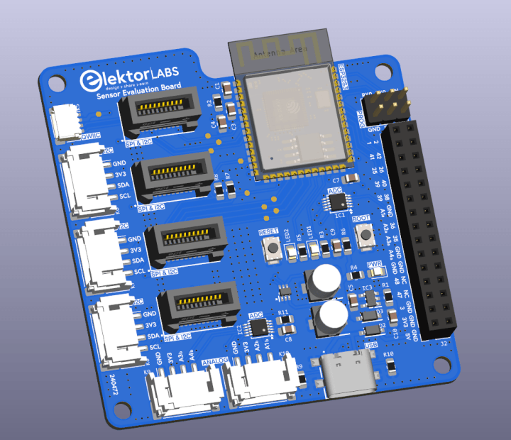
Lately, my focus has been on developing a Sensor Evaluation Board—a versatile platform designed for testing sensors and prototyping projects without the hassle of setting up individual configurations every time. How? By using edge card connectors that allow sensor modules to be swapped effortlessly. It’s like having a modular toolkit for IoT development!
Since most IoT projects rely on the reliable ESP32—thanks to its built-in WiFi, Bluetooth, and a vibrant community—it became the natural choice for this board. However, the ESP32’s ADC accuracy leaves something to be desired. To address this, I’ve included two ADS1015 12-bit ADCs for precise analog measurements. And because convenience is key, the board also features Grove connectors, making it a breeze to connect various sensors.
The design files are off for manufacturing, and I’m eagerly awaiting the PCBs. The first soldering session and testing will be the real moment of truth—stay tuned for the results!
AmpVolt Project: Version 2.0
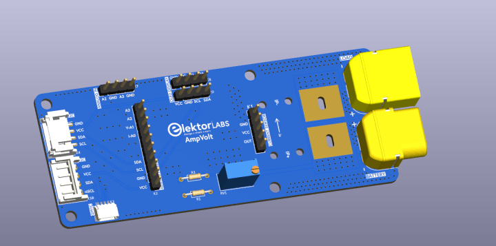
Encouraged by the positive feedback from readers and driven by the constant urge to improve, I’ve started working on the second version of the AmpVolt Project. And yes, it’s going to be bigger and better. This version will be capable of measuring over 100A and up to 60V. How? By switching from the traditional shunt resistor method to the more advanced Hall Effect current measurement.
I can’t spill too many beans just yet, but I believe it will be worth the wait. The full breakdown will be featured in an upcoming edition of Elektor Magazine. Until then, here’s a little teaser to keep the curiosity alive.
Stay tuned for more updates as these projects progress!
Jean-François Simon (Engineer, Elektor)
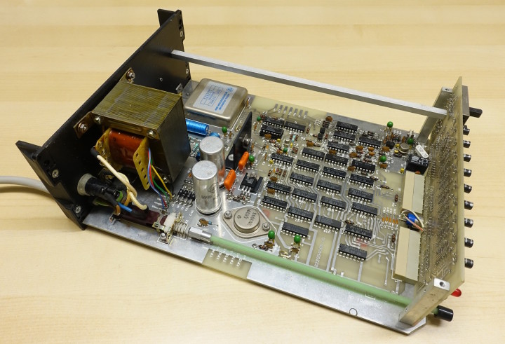
What’s new in the lab? Recently, I’ve been interested in frequency measurement. I came across an intriguing find on the classifieds and couldn’t resist buying it: an Enertec Schlumberger 2610 frequency counter. It immediately caught my eye, with a plexiglass front panel that, while charming, is very prone to scratches and fingerprints. To top it off, the labels are in French, adding to its old-school charm.
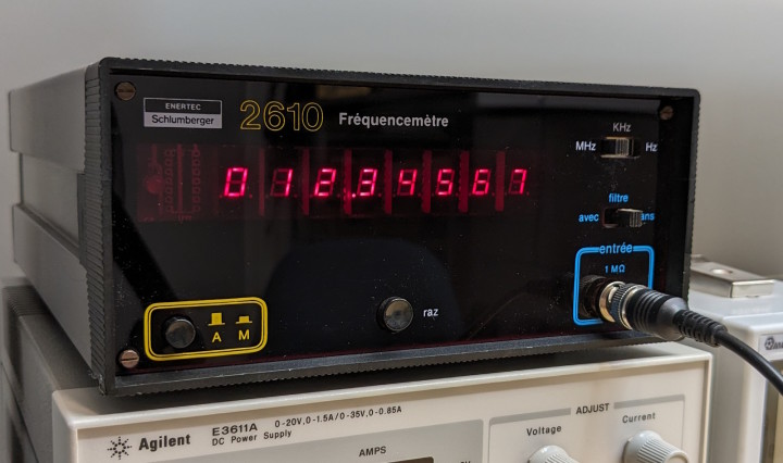
The internal construction is beautiful too. Judging by the markings on the integrated circuits, it was likely built around 1983. Unfortunately, as is often the case with this brand, documentation is nearly impossible to find. From what little information I’ve gathered, it’s rated for a maximum of 120 MHz, but that’s about all I know. If anyone has the manual, please get in touch!
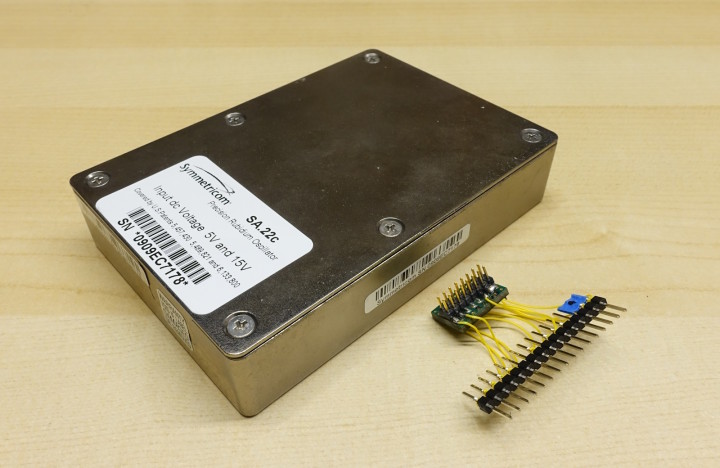
While the 2610 is cool, it might fall short for some of my upcoming projects. As it turns out, I recently acquired a 10 MHz rubidium oscillator (a Symmetricom SA.22c), most likely salvaged from a decommissioned mobile base station. It’s a bit quirky: all its inputs and outputs are located on the underside, which also needs to accommodate a heatsink. On top of that, it uses a 2mm dual-row connector, less common than the standard 2.54mm. Thankfully, I could find a suitable connector in my pile of scrap PCBs. I just extracted the piece of PCB with the connector soldered on it using a diamond wheel, and in no time I had a temporary adapter that allowed me to test the oscillator. A more polished and permanent solution is of course on my to-do list.
The oscillator’s 10 MHz output will serve as an external reference for another future frequency counter—likely a FA-2 from BG7TBL —since I’ll soon need to check a signal, a bit higher in frequency than what I usually deal with, at 3805 MHz. This will hopefully help me to repair a spectrum analyzer.
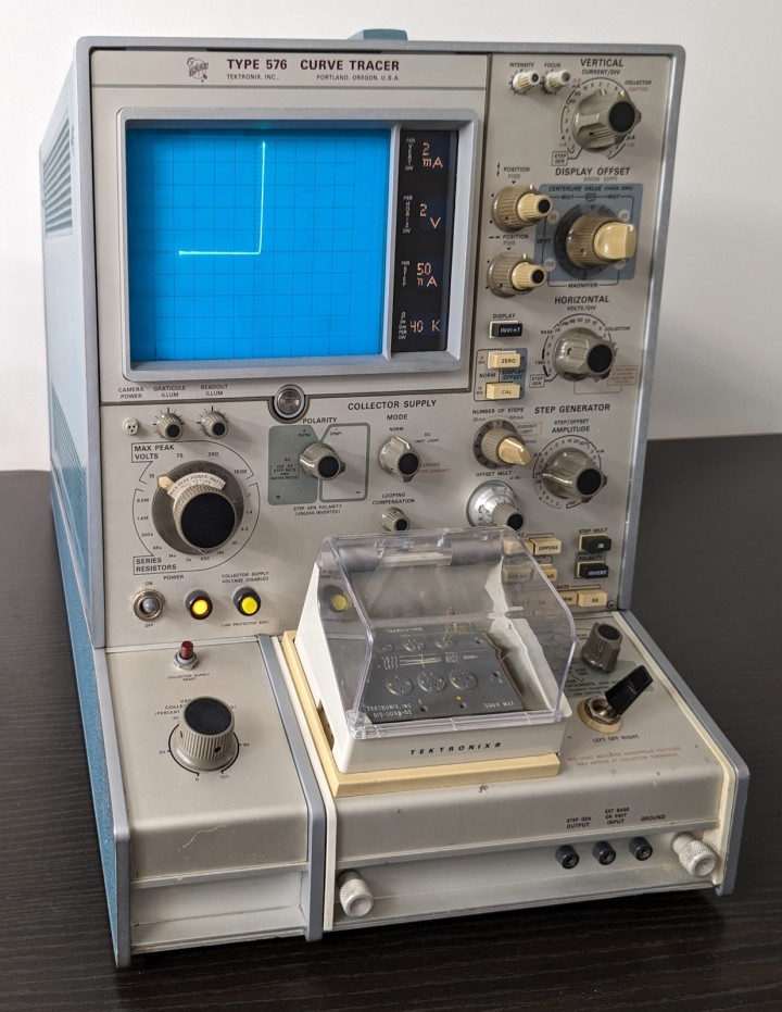
To round off this chapter of “new additions to the lab,” here’s one of my latest treasures: a Tektronix 576 curve tracer. This specific unit appears to be from the early production years, likely 1969 or 1970. While the instrument seems functional at first glance, a full check-up is in order. All the original electrolytic capacitors are still there, I suspect some of them could need replacing. The good news is that the service manual is very well made; that will definitely help me a lot. Stay tuned for updates in one of the future installments of Lab Notes!
Explore More Lab Notes and Electronics
Want to learn more about ESP32, microcontroller projects, or electronics in general? Check out all the educational videos and tap into the knowledge of experts on our Elektor YouTube channel and our Elektor Industry YouTube channel. Subscribe to Elektor's newsletter to receive a regular flow of expert tech knowledge and interesting perspectives.




Discussion (0 comments)