Elektor Lab Notes 23: Wireless Audio, Power Supplies, Elektor Formant and More
on

Jens Nickel (Editor-in-Chief, Elektor)

Pretty Fast Radio Modules: In Lab Notes 21, I reported on my experiments with digital wireless audio transmission. Since then, I’ve made some progress using ESP-NOW, which operates on the PHY layer of WiFi but without the usual WiFi overhead. This allows for lower power consumption and faster transmissions. My measurements showed that packets can be sent from one ESP32 to another in about 2 ms, which is pretty good and makes it possible to synchronize the ESP modules together. I believe this protocol is a great innovation from Espressif, as it leverages the built-in WiFi interface of an ESP32 or an ESP8266 without requiring additional radio modules. However, using WiFi channels has its downsides. If you live in a densely populated area, like I do, finding a spot without heavy WiFi traffic is nearly impossible. To maintain a reliable wireless audio connection, I had to increase the buffer size in my audio receiver significantly, which, of course, introduced latency — which is, of course, the enemy in audio transmissions. Ultimately, I managed a stable connection with 20 ms of delay, which is already questionable for precise beat matching in DJ setups. Reducing the buffer size got me down to 12 ms, but that still isn’t great, especially considering the additional delay caused by sound waves traveling from the speakers to your ears. On top of that, interference from other WiFi traffic severely limited the range, even outdoors.
So, while I was happy it worked at all, I wasn’t completely satisfied. A few days after testing in a park in Cologne, I was browsing AliExpress when I stumbled upon small modules with nRF24 chips from the well-known manufacturer Nordic. That rang a bell — I recalled some Elektor projects using them. The 32-byte packet size didn’t sound very promising, but I ordered a few anyway and started testing. It turned out that sending packets with just 16, 12, or even fewer audio samples resulted in a surprisingly good and stable audio connection, with significantly less interference from WiFi. That brought latency down to around 6 ms. However, final tests are still pending, and there’s a tradeoff: data rate. At least with my setup, using an external nRF24 library and Espressif’s I²S drivers in a straightforward way, I was limited to 32 kSamples/s and one audio channel. Fortunately, running two parallel connections wasn’t an issue, so I “just” doubled the hardware to achieve stereo. (The image above shows one of the sender prototypes with the RF module in the foreground.) More updates to come…
Digital Volume Control: On Elektor Labs and in these Lab Notes, I’ve previously written about a pet project I’m working on with a friend: independent loudspeaker stations with a built-in battery, amplifier, wireless audio receiver, and remote volume control. Since then, we’ve made progress: building wooden enclosures and replacing the original 80-euro amplifiers with even more affordable preamp and power amp modules. The latter, sourced from the Far East for around 25 euros each, support bridged mono and stereo configurations and even come with built-in fans. However, we’re still relying on an Alps motorized potentiometer and quite a bit of additional circuitry, which isn’t cheap and takes up valuable space. While experimenting with I²S modules for wireless audio, I had an idea: why not handle volume control digitally? Since the audio samples arrive as 16-bit integers, a simple multiplication is enough to adjust the volume. To avoid losing resolution, I took inspiration from a project featured in the upcoming March and May editions — an FPGA audio player by our author Christian Nöding. His approach involves converting audio to 32-bit before performing calculations, so I did the same. Now, my I²S player receives the 16-bit samples wirelessly, expands them to 32-bit, and applies digital volume control. The result? A solution that sounds great, both literally and figuratively. This opens the door to a streamlined board that not only receives audio wirelessly but also handles volume control, reducing both size and cost. As a spin-off, I’m planning to present a versatile audio board featuring an I²S sampler and player, an ESP32-S3, and an nRF24 module (see above) in this summer’s Circuit Special. The first prototype, with some help from my colleague Saad, is already in progress.
Jean-François Simon (Engineer, Elektor)
Switching power supply noise: what makes some switching power supplies produce an audible noise when supplying current? Let’s take a practical example. My ZD-915 desoldering station (as well as its more recent variants, the ZD-985, ZD-8915, and others) is powered by an 18V power supply, supposedly capable of delivering a maximum of 12A. When the desoldering gun is heating up, the power supply emits a rather unpleasant whine. This noise isn’t actually very bothersome because, in any case, the vacuum pump makes an even louder noise when the gun is activated. But it’s enough to make me want to dig deeper into the topic! To allow the power supply to rest outside the case and make bench measurements easier, I added a temporary heatsink and extended the wires.
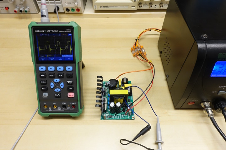
This modification also allows for the installation of another power supply if needed, to compare measurements and acoustic noise levels. Since the original power supply also contains the MOSFET that switches the desoldering gun’s heating element on and off (an STP60NF06FP, capable of handling 60V and 30A), it is necessary to replicate this part of the circuit externally on a piece of perfboard.
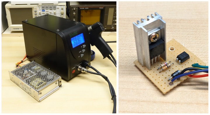
The original power supply for the desoldering station, labeled ZD-P150, is based on the ON Semiconductor FSCQ1565RT integrated circuit. This IC integrates both the switching controller and the main MOSFET that switches the transformer’s primary side, all within a single TO-220 package. Be extremely careful when taking measurements on the primary side of a power supply: never connect your oscilloscope directly, always use an isolated differential probe or a battery-powered isolated scope. By passing a piece of wire through the ferrite core of the transformer and connecting it to the oscilloscope probe, it is possible to capture an image of the voltage in the winding (in blue). The yellow trace is the PWM signal controlling the heating element.
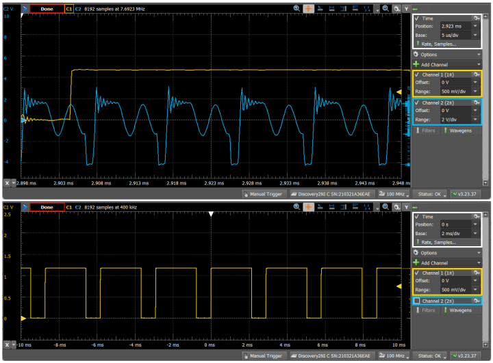
The signal shape matches the one described in the very informative FSCQ1565RT datasheet; the power supply operates in extended quasi-resonant mode. When powering a continuous resistive load, it’s silent. In the desoldering station, the audible noise most likely originates from the PWM control of the heating element, which the manufacturer has set to around 340 Hz. This frequency, along with several of its harmonics, falls within the audible range. When the heating element is active, the power supply delivers about 3.5 A, compared to almost zero when it is off. During transitions, the FSCQ1565RT adjusts its oscillation frequency to improve efficiency under low loads. The 340 Hz modulation is heard in the transformer winding, which has not been impregnated with varnish and is free to vibrate.
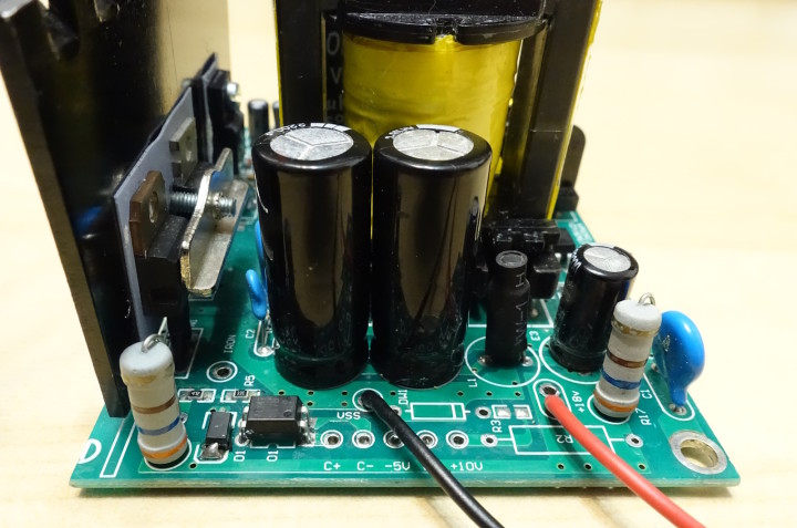
The most reasonable approach is, of course, to leave the desoldering station as it is — after all, it’s just an inexpensive tool. However, for the sake of argument, here are some possible solutions to improve the situation:
- Impregnating the transformer with varnish, such as the 4228A from MG Chemicals
- Checking the filtering. Currently, it’s done using a Pi filter: 4400 µF / 2 µH / 470 µF. By the way, this inductor is made of tiny wire and seems quite inadequate for 12 A to me... Time to do some calculations! There may be room for optimization.
- Inserting an Arduino or similar circuit upstream of the optocoupler to convert the 340 Hz PWM to a much lower frequency.
- Using a different power supply instead. This would also allow for faster heating by using a 24 V power supply (the rated voltage of the heating element) instead of 18 V. The manufacturer probably chose 18 V as a compromise to increase reliability; by undervolting the heating element, the current it consumes is reduced, which puts less strain on the power supply.
Have fun, and happy desoldering!
Roberto Armani (Senior Editor, Elektor)
In the late 1970s, the first analog audio synthesizers appeared on the music scene and soon achieved global success through many artists and music groups of the time. They all had a modular structure and allowed different types of connections between modules to achieve the desired results, as well as a common feature: costing a fortune!Elektor could not resist the challenge of making a design that was modular, versatile and, most importantly, affordable for readers.
Thus was born the Formant, a project spread over many issues of the magazine, which was an extraordinary success and kept many enthusiasts for days, weeks and months with...soldering iron in hand!
At Elektor, we bought one from a German engineer, who was selling it as not working, but in overall good shape.
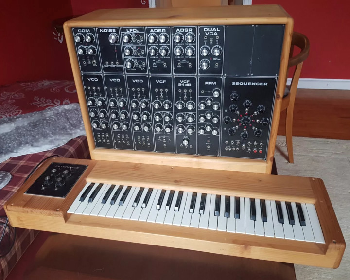
- 3 VCO modules
- 1 VCF standard module
- 1 VCF 24 dB module
- 1 RFM module
- 2 ADSR modules
- 1 Dual VCA module
- 1 LFO module
- 1 Noise module
- 1 COM module
- 1 Keyboard Interface
- 1 Sequencer Module (not Elektor original)
- 1 Analog power supply (+ 15 V, - 15 V, + 5 V)
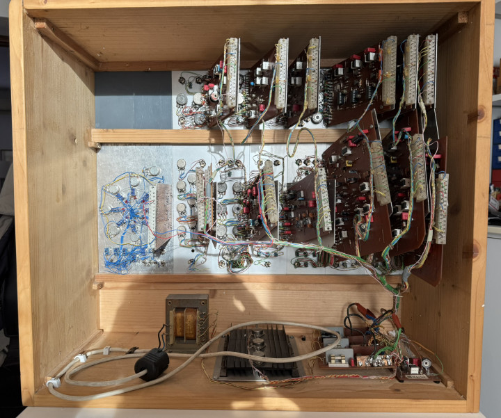
Given the unfortunate start, an extensive recovery plan is needed, including:
- Repair of the wooden case, with bonding of the cleavages produced by the transport shocks.
- Repainting of both the Formant and the keyboard cases.
- Repair of the warped mechanics of the modules.
- Modification of the modules oriented at 60° (Originally installed in a tilted console) to the needed 90° standard.
- Searching for mechanical damage on PCB and components, on each module.
- Temporary reassembly and preliminary testing.
- Troubleshooting on defective/faulty modules, with repair.
- Final reassembly with overall testing.

the angle between the front panel of this ADSR module and the board support should be 90°...(see a repaired module in background)
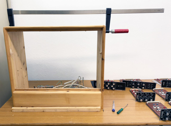
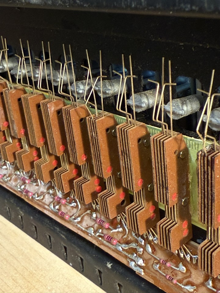
After seeing this, not intimidated at all, we jumped into the fray and accepted the challenge of bringing this glorious Elektor project back to life, if possible, after 45 years!
Will we succeed?
To find out, you just have to...stay tuned!
Explore More Lab Notes and Electronics
Want to learn more about Arduino, test and measurement, microcontroller projects, or electronics in general? Check out all the educational videos and tap into the knowledge of experts on our Elektor YouTube channel and our Elektor Industry YouTube channel. Subscribe to Elektor's newsletter to receive a regular flow of expert tech knowledge and interesting perspectives.


Discussion (0 comments)