

Elektor Uno R4 [150790]
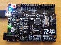
The Elektor Uno R4 is an Arduino Uno R3 equiped with the ATmega328PB-AU featuring 2x USART, 2x I2C and 2x SPI and much more.
This board is an evolution of the Arduino Uno R3 board. Identical form factor as the Uno but based on the ATmega328PB-AU, this board has much more features than the Uno. Because it is backwards compatible you can think of it as revision 4 of the Uno, which is why we called it the R4.
The circuit of the R4 is pretty close to the Uno. One of the main differences is the USB-to-serial converter for which I used an FTDI chip instead of another AVR. This saves on firmware/driver maintenance & device programming. The power supply is a bit stronger than on the Uno and of course we provided four extra connector pins to accomodate Port E of the ATmega328PB.
Here is a table that shows the main differences between the R3 and the R4.
There are some more differences, like the touch controller. Check the datasheet for details.
Drawing up the schematic was easy enough, the hard work is in the software. Because the Arduino IDE does not know about the ATmega328PB I had to build a Boards Package that provides the toolchain. How to do this properly is unfortunately not very well documented, making this a complicated task. Also the SPI and Wire libraries had to be modified to support multiple peripherals. More details about the IDE integration can be found in the Elektor Magazine article published in June 2016.
There are (unfortunately) several Boards Packages. There is one for Windows only that includes a full toolchain (Linux and Mac users can use it in a virtual machine), there are two others for Windows, Linux and OSX that do not need a toolchain (use these if you can). The Boards Packages can be downloaded from the Elektor.Labs space at GitHub.
Update November 18, 2020
The Elektor Uno R4's Boards Package has been updated to V2.0.0.
To install the Elektor Uno R4, paste the link https://github.com/ElektorLabs/Arduino/releases/download/v1.0.1/package_elektor_uno_r4_1_8_x_index.json in the 'Additional Boards Manager URLs' box of the IDE's Preferences window.
Tested with Arduino IDE 1.8.13
Update September 8, 2016: The Boards Packages have been updated:
With these new packages you have access to an 8 MHz version of the bootloader for boards running on the internal RC oscillator or on an external 8 MHz crystal, good for low-voltage applications. In the IDE you can choose between 16 MHz and 8 MHz R4 boards.
Note that the Boards Packages also include the source code for the bootloader plus batch files that show you how to compile it allowing you to create your own custom bootloader. If you need a suitable toolchain (Windows only), you can download avr-gcc-4.9.2-i686-mingw32.zip from the Elektor.Labs space at GitHub.
Update August 10, 2016: a special Boards Package for Arduino IDE 1.6.10 has been added to the repository. Use https://github.com/ElektorLabs/Arduino/releases/download/v1.0.1/package_elektor_uno_r4_1_8_x_index.json
This package also works with 1.6.11 and hopefully also the future versions 1.6.1x.
Update June 23, 2016: a new R4-only Boards Package supporting Windows, Linux and OSX is now also available. This package does not need a new toolchain. See below for details.
Installation
Use the Arduino IDE (v1.6.6 or higher, do not use an IDE from arduino.org) Boards Manager to install this package, as follows:
3V3 & battery operation
Officially the MCU is not specified for 3V3 @ 16 MHz, but for me it works fine. If it doesn't, it is easy enough to replace the crystal by an 8 MHz one. An even simpler solution is to leave the 16 MHz crystal on the board, but reprogram the fuses (extended = 0xf5, high = 0xde, low = 0xe2) to make the MCU use its internal 8 MHz oscillator.
For other low voltage sources (i.e. battery) disconnect the MCU VCC line by opening JP1 (and removing R7 if present). Connect the external voltage source in this case to the middle pin of JP1 (or to IOREF on K5).
Important
New peripherals in sketches
The Elektor Uno R4 has more hardware peripherals than the R3 and so the Arduino libraries have been upgraded to support them. In your sketches you can now use:
Bootloader & fuses
The Elektor Uno R4 bootloader can, of course, be found on GitHub, and it is included in the Boards Package so if you installed that you already have it on your computer, but for your convenience it is also available in the download section below. This download includes avrdude and an example command line to make things easier for you.
An 8 MHz bootloader is included in the Boards Package, ex. c:\Users\[USER]\AppData\Local\Arduino15\packages\Elektor-Uno-R4-for-Arduino-1.6.10\hardware\avr\1.0.1\bootloaders\R4\optiboot_elektor_uno_r4_8mhz.hex
The fuses should be set like this (like an Arduino Uno R3):
Extended fuse byte: 0xf5 (or 0x05 depending if avrdude gets it or not)
High fuse byte: 0xde
Low fuse byte: 0xff (0xe2 for 8 MHz internal oscillator)
Video
The circuit of the R4 is pretty close to the Uno. One of the main differences is the USB-to-serial converter for which I used an FTDI chip instead of another AVR. This saves on firmware/driver maintenance & device programming. The power supply is a bit stronger than on the Uno and of course we provided four extra connector pins to accomodate Port E of the ATmega328PB.
Here is a table that shows the main differences between the R3 and the R4.
| Arduino Uno R3 | Elektor Uno R4 | |
|---|---|---|
| USART | 1 | 2 |
| SPI | 1 (2 counting USART) | 2 (4 counting USART) |
| I2C | 1 | 2 |
| GPIO | 20 | 24 |
| Analog in | 6 | 8 |
| PWM | 6 | 9 (10 internal) |
| Timer | 6 | 9 |
| OCM | - | 1 |
There are some more differences, like the touch controller. Check the datasheet for details.
Drawing up the schematic was easy enough, the hard work is in the software. Because the Arduino IDE does not know about the ATmega328PB I had to build a Boards Package that provides the toolchain. How to do this properly is unfortunately not very well documented, making this a complicated task. Also the SPI and Wire libraries had to be modified to support multiple peripherals. More details about the IDE integration can be found in the Elektor Magazine article published in June 2016.
There are (unfortunately) several Boards Packages. There is one for Windows only that includes a full toolchain (Linux and Mac users can use it in a virtual machine), there are two others for Windows, Linux and OSX that do not need a toolchain (use these if you can). The Boards Packages can be downloaded from the Elektor.Labs space at GitHub.
Update November 18, 2020
The Elektor Uno R4's Boards Package has been updated to V2.0.0.
- The ATmega328PB is now fully supported by the Arduino IDE's default AVR toolchain. This makes installation of the Elektor Uno R4 much faster as there is no longer a special toolchain to download. It makes the board also future proof as new toolchain features are used automatically.
To install the Elektor Uno R4, paste the link https://github.com/ElektorLabs/Arduino/releases/download/v1.0.1/package_elektor_uno_r4_1_8_x_index.json in the 'Additional Boards Manager URLs' box of the IDE's Preferences window.
Tested with Arduino IDE 1.8.13
Update September 8, 2016: The Boards Packages have been updated:
- Fix SoftwareSerial problem (found working up to 115,200 baud with an MCU clock of 16 MHz)
- Add Optiboot 8 MHz bootloader
- Add 8 MHz boards
With these new packages you have access to an 8 MHz version of the bootloader for boards running on the internal RC oscillator or on an external 8 MHz crystal, good for low-voltage applications. In the IDE you can choose between 16 MHz and 8 MHz R4 boards.
Note that the Boards Packages also include the source code for the bootloader plus batch files that show you how to compile it allowing you to create your own custom bootloader. If you need a suitable toolchain (Windows only), you can download avr-gcc-4.9.2-i686-mingw32.zip from the Elektor.Labs space at GitHub.
Update August 10, 2016: a special Boards Package for Arduino IDE 1.6.10 has been added to the repository. Use https://github.com/ElektorLabs/Arduino/releases/download/v1.0.1/package_elektor_uno_r4_1_8_x_index.json
This package also works with 1.6.11 and hopefully also the future versions 1.6.1x.
Update June 23, 2016: a new R4-only Boards Package supporting Windows, Linux and OSX is now also available. This package does not need a new toolchain. See below for details.
Installation
Use the Arduino IDE (v1.6.6 or higher, do not use an IDE from arduino.org) Boards Manager to install this package, as follows:
- Open the Arduino IDE's Preferences dialog: File -> Preferences
- Windows users only (this package includes avr-gcc 4.9.2): add the URL https://raw.githubusercontent.com/ElektorLabs/arduino/master/package_elektor_boards_index.json to the edit box "Additional Boards Manager URLs". (It is possible to have multiple URLs as long as you separate them with commas.) This URL is long and finishes with "json", make sure you copy all of it. You can also copy it from here.
- Windows/Linux/OSX users (this package works with the default Arduino toolchain): add the URL https://raw.githubusercontent.com/ElektorLabs/arduino/master/package_elektor_uno_r4_index.json.
Arduino IDE 1.6.1x and 1.8.x users must use https://github.com/ElektorLabs/Arduino/releases/download/v1.0.1/package_elektor_uno_r4_1_8_x_index.json - Open the IDE's Boards Manager: Tools -> Board -> Boards Manager
- As Type (upper left corner) select Contributed. You should now see at least one entry for Elektor boards.
- Click on the entry that you want to install to make the install button appear.
- Click the Install button to install the boards.
- Close the dialog when done.
- Now when you open the available boards list (Tools -> Board) there will be a header "Elektor Labs" followed by the Elektor boards. Choose the one you need.
3V3 & battery operation
Officially the MCU is not specified for 3V3 @ 16 MHz, but for me it works fine. If it doesn't, it is easy enough to replace the crystal by an 8 MHz one. An even simpler solution is to leave the 16 MHz crystal on the board, but reprogram the fuses (extended = 0xf5, high = 0xde, low = 0xe2) to make the MCU use its internal 8 MHz oscillator.
For other low voltage sources (i.e. battery) disconnect the MCU VCC line by opening JP1 (and removing R7 if present). Connect the external voltage source in this case to the middle pin of JP1 (or to IOREF on K5).
Important
- The bootloader must be adapted to the MCU clock frequency, otherwise the baud rate will be wrong. 8 MHz Optiboot bootloaders are included in the Elektor Uno R4 Boards Package distribution, ex. c:\Users\[USER]\AppData\Local\Arduino15\packages\Elektor-Uno-R4-for-Arduino-1.6.10\hardware\avr\1.0.1\bootloaders\R4\optiboot_elektor_uno_r4_8mhz.hex.
- To use the internal 8 MHz oscillator set the low fuse byte to 0xe2.
- Make sure R7 is not mounted when you want to power the MCU from 3V3 or a battery.
New peripherals in sketches
The Elektor Uno R4 has more hardware peripherals than the R3 and so the Arduino libraries have been upgraded to support them. In your sketches you can now use:
- Serial and Serial1
- Wire & Wire1 (or I2C0 and I2C1, include the Wire library), Wire and I2C default to I2C0
- SPI0 and SPI1 (include the SPI library), SPI defaults to SPI0
- digitalRead/Write now also work on pins 20 to 23 (port E)
- analogWrite now also works on pins 0, 1 and 2
- analogRead accepts A6 and A7
Bootloader & fuses
The Elektor Uno R4 bootloader can, of course, be found on GitHub, and it is included in the Boards Package so if you installed that you already have it on your computer, but for your convenience it is also available in the download section below. This download includes avrdude and an example command line to make things easier for you.
An 8 MHz bootloader is included in the Boards Package, ex. c:\Users\[USER]\AppData\Local\Arduino15\packages\Elektor-Uno-R4-for-Arduino-1.6.10\hardware\avr\1.0.1\bootloaders\R4\optiboot_elektor_uno_r4_8mhz.hex
The fuses should be set like this (like an Arduino Uno R3):
Extended fuse byte: 0xf5 (or 0x05 depending if avrdude gets it or not)
High fuse byte: 0xde
Low fuse byte: 0xff (0xe2 for 8 MHz internal oscillator)
Video
Discussion (26 comments)

Michel BLOISE 1 year ago
Have you tried to use this Elektor R4 to burn the Bootloader into a NANO 328PB, using the "Arduino as ISP" example of the IDE ??
The regular UNO R3 is NOT able to burn a bootloader is a NANO 328PB: it works only with a NANO 328P.
Thank you for your reply,
The regular UNO R3 is NOT able to burn a bootloader is a NANO 328PB: it works only with a NANO 328P.
Thank you for your reply,
Reply
Show more
0 Comment(s)

Peter Lambrechts 4 years ago
I got y this error while compiling a sketch after update the R4 board
The IDE version is
Arduino: 1.6.7 (Windows 10), Board:"Elektor Uno R4 @ 16 MHz"
avr-g++: error: unrecognized argument in option '-mmcu=atmega328pb'
avr-g++: note: valid arguments to '-mmcu=' are: at43usb320 at43usb355 at76c711 at86rf401 at90c8534
and a lot other mcu's
exit status 1
Error while compiling
If I use another board the compiler does'nt complain and no errors are produced
Reply
ElektorLabs 4 years ago
Please upgrade the Arduino IDE if you can. The current version is 1.8.13, the current Elektor Uno R4 Boards package v2.0.0 does not work with most older IDE versions. If for some reason you cannot upgrade the IDE, please use the old boards package v1.0.1. Do not install v2.0.0.
Reply
Show more
1 Comment(s)

brehe 4 years ago
Hi,
here is the answer to the question I raised one day ago: In case I force the servo to turn für several 10 degrees, the 5 V power supply drops by approx. 1 V as my scope indicates. Solution: I let the servo turn in small steps and by adding a short waiting period between the steps.
Best regards
-brehe
Reply
Show more
0 Comment(s)
brehe 4 years ago
Hi,
I tried to control a servo using a R4. My observations: The lever turns by some 10 degrees, stops für a while (approx. 1 s) , than turns again, another stop and than it gets to its final position (hopefully, not always). This is not as it should be and differs from the observations I made with a UNO clone using exactly the same configuration: Everything is fine.
Does somebody has an explanation?
For the records: Arduino 1.8.12
Elektor Uno R4 for Arduino 1.8.x Version 1.0.0
Best regards
-brehe
Reply
Show more
1 Comment(s)
brehe 5 years ago
I have 2 Ethernet shields (both of them are clones from different manufactureres) which work fine in combination with Arduino UNO. Once I combine them with Elektor Uno R4 I get in trouble:
The same sketch which works fine with the UNO cannot be uploaded successfully after compiling (1.8.10). Error message: "Beim Hochladen ist ein Fehler aufgetreten". This happens with both shields.
Compiling and uploading works fine with no Ethernet shield mounted.
When mounting Ethernet shield #1 after uploading the shield seems to work fine (LEDs are flickering) but the application does not work: Pinging the board fails.
When mounting Ethernet shield #2 after uploading the LED LINK and PWR stay ON permanently, current consumption R4 plus Ethernet shield is in the range 10 mA (Ethernet shield #1: 200 mA).
I would be happy if this problem can be solved. Using the UNO without knowing what causes the problems with the R4 is no acceptable solution. I hope you will agree.
Thank you in advance.
Reply

ClemensValens 5 years ago
This problem is probably due to the ICSP connector on the R4 that (unfortunately) is rotated 180 degrees. Normally this doesn't pose any problems, except in the case of a shield like the Ethernet shield that uses the ICSP connector instead of the standard Arduino extension connectors. You can either modify the R4 or the Ethernet shield to work around this problem (or not use the R4 at all).
Reply
Show more
2 Comment(s)

Alois Segner 5 years ago
I came across an interested project to try with the Uno R4, but no successful compiling with the delivered libraries. The project works with the Arduino Uno Standard with no error.
After some research I found the hint to use the compiler option '--std=c++11!
Now I find no place or file to enter or try those options with the Elektor Uno R4 Hardware in the Arduino 1.8.10 or other.
Please indicate how to enter the options in this case or another workaround. The compiler options a very useful also for other cases.
Thanks in advance.
AS
Reply
Thomas Beck 5 years ago
Additional compiler options can be entered in file platform.txt. This file is in folder C:\Users\YOUR USER NAME\AppData\Local\Arduino15\packages\Elektor-Uno-R4-for-Arduino-1.8.x\hardware\avr\1.0.0.
You can add this option to compiler.cpp.flags or compiler.cpp.extra_flags. Another solution is to create a platform.local.txt file with just one entry compiler.cpp.extra_flags=-std=c++11 and put this file into the same directory as platform.txt. This is how I solved this problem in my project OBD2 for Arduino which supports the Elektor Uno R4. In platform.local.txt, I have added option -std=gnu++11 along with several other options and further project specific defines.
You can add this option to compiler.cpp.flags or compiler.cpp.extra_flags. Another solution is to create a platform.local.txt file with just one entry compiler.cpp.extra_flags=-std=c++11 and put this file into the same directory as platform.txt. This is how I solved this problem in my project OBD2 for Arduino which supports the Elektor Uno R4. In platform.local.txt, I have added option -std=gnu++11 along with several other options and further project specific defines.
Reply
Show more
2 Comment(s)

Janez Majdic 5 years ago
Hello, I took my Elektor Uno R4 (2016) from "the dust", to help my son at his Arduino learning, but I run into the same problem as Thomas Beck did back in July, 2018. I can't upload sketch to Elektor Uno R4. I did all installations by "the book", but no success. Neither did Mr.Beck's soultion helped with libusb0.dll. I'm using Arduino 1.8.9 on Windows 10 Enterprise 64bit version, with latest upgrades, and all workds well, until uploading. I attached Error.txt, but there is not much to see. Any suggestions are welkome!
Reply
Janez Majdic 5 years ago
At first, thank you ElektorLabs and Hans for helping me out. Now, after I finally connect all as it should be, my Elektor Uno R4 came alive! Excuse me for my senior moments, but it's been quite a long time ago, I played with this "toys".
Now I’m passing all I know about, to my 16 year old son. Kind regards from me and Thank’s again.
Now I’m passing all I know about, to my 16 year old son. Kind regards from me and Thank’s again.
Reply
ElektorLabs 5 years ago
Please note that the programming Uno must reset the R4, not the other way around. The way you had wired it (according to your photograph) was the wrong way around. So pin 10 of the programming Uno should go to Reset on the R4. There should be no wires going to the reset pin of the programming Uno. If you did this correctly and it still doesn't work, then try HaSch's capacitor suggestion.
Reply

Janez Majdic 5 years ago
I read this: https://www.arduino.cc/en/Tutorial/ArduinoISP, I realize that Arduino Uno can be used as SPI programmer conected on old way to Elektor Uno R4 to burn bootloader.
I did that as you can see on attached picture and the result is in the second part of attached txt file. The avrdude files are from 150790-elektor-uno-r4-bootloader.zip file.
I did that as you can see on attached picture and the result is in the second part of attached txt file. The avrdude files are from 150790-elektor-uno-r4-bootloader.zip file.
Reply
Janez Majdic 5 years ago
Thank you for your effort to deal with this problem. I checked all joints from K1 to IC2 and to IC4 with Ohmmeter, and are all OK. I also checked the joint to VCC and GND for IC2 and IC4. I didn't play with soldering iron, because at my 71, hands are to shaky! I don't have tools to reprogram bootloader, neither have FTDI-type USB-serial cable/adapter to reset Arduino. So I'm put out of idea what to do next. Can I send it to you somewhere to deal with it, because as such, it is useless for me. Me and my son have a few other Arduinos to play with, so this one, though it is interesting, is expandable.
Regards!
Regards!
Reply
ElektorLabs 5 years ago
OK, so we can exclude the Arduino IDE installation & the boards package etc. as you seem to have a serial port problem instead. The board does not respond to the "are-you-there?" query from avrdude. It resets OK, though. Either it does not receive the query and so it will not respond or it receives the query but its response doesn't get through.
The USB connection seems allright since the board is detected OK and resets come through.
If you have the tools for it you may try to reprogram the bootloader. You can also try connecting an FTDI-type USB-serial cable/adapter to Arduino pins 0 & 1 and reset. That would bypass the on-board FTDI chip. If that works the bootloader is OK.
More probable though is that you have a bad solder joint (or via) somewhere on the serial port (between the MCU and the FTDI chip, R13, R14, chips included). Touch up the solder joints a bit with a fine soldering iron. (IC2 pins 4 and 20, R13, R14, IC4 pins 30 & 31, don't short anything.)
Reply
Janez Majdic 5 years ago
Yes OK, I understand. So I went to our club, where we have new PC with Windows 10 Enterprise, with all latest upgrades. This PC never saw any Arduino microprocessor or software, and we use it only for administration. So I installed Arduino 1.8.9, put https://github.com/ElektorLabs/Arduino/releases/download/v1.0.1/package_elektor_uno_r4_1_8_x_index.json
in URL for Additional Boards in Preferences. At Board Manager I installed Elektro uno R4 for Arduino 1.8.x. Select Elektor Uno R4 @ 16 MHz, and select COM Port, I can also see in Device Manager, when I connect Elektor Arduino R4 to USB Port.
When I connect EAR4 on USB port, TX light blinks twice. When I Upload the Sketch, when compilation is over, and uploads really begin, first blinks TX, than RX 3 times very quick, and then every 10 seconds 9 times, after that "An error occurred while uploading the sketch" message came up! Pressing Reset button, Tx blinks. This scenario goes on, no matter wich PC I use, old one or new "inocent" one! In attachment, there is Error file from new PC.
Reply
Janez Majdic 5 years ago
Now I removed/uninsstall everithing about Arduino, and made fresh install Arduino 1.8.9 on my Notebook. Put this: https://github.com/ElektorLabs/Arduino/releases/download/v1.0.1/package_elektor_uno_r4_1_8_x_index.json
into Preferences Additional Boards Manager URL. Install Elektor Uno R4 for Arduino 1.8.x, select Elektro Uno @ 16MHz and COM Port. Error is still here! Attached Error file.
into Preferences Additional Boards Manager URL. Install Elektor Uno R4 for Arduino 1.8.x, select Elektro Uno @ 16MHz and COM Port. Error is still here! Attached Error file.
Reply
ElektorLabs 5 years ago
Looking closer at your error file, I noticed that you selected the 8 MHz version of the Elektor Uno R4. Are you sure about that? The default R4 as we manufactured it runs at 16 MHz. The 8 & 16 MHz versions do not use the same bootloader serial port speed, which could explain why your sketch won't upload.
FYI:
1. I did a clean install of Arduino 1.8.9 using the 'Windows Installer, for Windows XP and up'.
2. Installed the Elektor Uno R4 Boards package using this link as 'Additional Boards Manager URLs' in the Preferences dialog:
https://github.com/ElektorLabs/Arduino/releases/download/v1.0.1/package_elektor_uno_r4_1_8_x_index.json
3. As board, I selected the 'Elektor Uno R4 @ 16 MHz'
4. Compiled and uploaded the BlinkWithoutDelay example and everything worked fine.
However, when I change the board to 'Elektor Uno R4 @ 8 MHz' I get this error (after waiting a minute or so):
An error occurred while uploading the sketch
Reply
Show more
1 Attachment(s)
14 Comment(s)

massimo cremonesi 7 years ago
Hi ,
I'm using elektor R4 card , I order to reduce the power consumption I've to enter in sleep mode when there are no serial communication and wake up when communication restart.
I'm able to enter in sleep mode but I not able to wake up the processor.
I've used the follow function but compiler, make error
ISR(USART0_RX_vect)
{
if (SleepFlag == true) {
sleep_disable();
SleepFlag = false;
}
please could you help me.
thank you in advance
MAssimo
Reply
ClemensValens 7 years ago
Start Frame Detection has its own interrupt vector USART0_START_vect (and USART1_START_vect) which is unknown to the basic Arduino core. However, it is available in our Uno R4 boards package. This means that you can provide your own ISR for it, like this:
ISR(USART0_START_vect)
{
}
You must, of course, set the SFDE and RX(S)IE bits. Unfortunately, the most recent datasheet does not mention where these bits live. In an older datasheet I found UCSR0D & UCSR1D (USART Control and Status Register n D) but these registers have disappeared meaning that this feature is no longer supported? They are also not in the register definition file. The registers are (were) at 0xc3 & 0xcb, so if you add these defines to your program you can use them as you use other registers & bits:
#define UCSR0D _SFR_MEM8(0xC3)
#define SFDE0 5
#define RXS0 6
#define RXIE0 7
#define UCSR1D _SFR_MEM8(0xCB)
#define SFDE1 5
#define RXS1 6
#define RXIE1 7
This is all untested and since it is undocumented, it may not work at all, and even result in unexpected/undesired behaviour. Please let us know if you manage to get this to work.
Reply

massimo cremonesi 7 years ago
Hi,
I'm sorry for less information in my previous request.
What I want use for microprocessor wake up from sleep state, is the USART start frame detector.
This feature is only available in ATMEGA328PB, and not in AT MEGA328P for this there are no information in internet, the only information about wake up systems, are using the external interrupts but in this case we need an additional input pin.
Please , have you idea how is possible to use this this USART start frame detector, if is possiblle with arduino IDE.
Thank you in advance
Massimo
Reply
ClemensValens 7 years ago
When asking for help, always provide as much information as possible. "compiler, make error" does not tell us anything.
Anyway, in your case the problem is probably that you try to redefine ISR(USART0_RX_vect) which is already defined in HardwareSerial0.cpp
This is not an R4 problem, but an Arduino feature. Please search the internet for "Arduino wake up on serial event" or something similar to find a solution to your problem.
Reply
Show more
4 Comment(s)

zozio 7 years ago
Hello,
I have been using using R4 board for several monthes.I use 1.6.7 IDE and 1.02 R4 package.
A new problem arose these days :
I could not manage to get pin change interrupts to work correctly on pins 20 (A6), 21 (A7) until I modified the "digitalPinToPCMSKbit(p)" macro in pins_arduino.h.
The conversion of boards's pin numbers into PCMCK3 bit numbers seemed to be wrong for these pin numbers. So I changed the macro cited above from the original
#define digitalPinToPCMSKbit(p) (((p)<=7)? (p) : (((p)<=13)? ((p)-8) : (((p)<=19)? ((p)-14) : ((p)<=21)? ((p)-17) : ((p)-22))))
to
#define digitalPinToPCMSKbit(p) (((p)<=7)? (p) : (((p)<=13)? ((p)-8) : (((p)<=19)? ((p)-14) : ((p)<=21)? ((p)-18) : ((p)-22))))
(I changed ((p)-17) to ((p)-18) if p == 20 and p == 21).
Doing so, everything goes well.
Anybody with the same problem ? Am I right ?
Thank's for answer and for this nice product.
Reply
Show more
1 Comment(s)

Bud 7 years ago
It would be nice to have the plain GNU toolchain command lines needed to build and burn a C program to the R4, without using an IDE (Arduino, Atmel Studio).
Reply
Bud 7 years ago
Great! That's exactly what I was looking for.
Years ago, I used an Atmel STK525 board and C to play around. I wrote a simple script to do the building. Now I'm looking for a modern board, but wish to still be able to program both boards with the same environment. Thus, my asking about the command lines for your R4.
I understand the appeal of Arduino as a platform, but also read about PlatformIO as an attractive alternative.
Any thoughts about the two eco-systems (at the hobbyist level), and in particular with R4?
Reply
ClemensValens 7 years ago
There is no such thing as an "entire command line" for an undefined project as it depends on the project. The simplest form would be this:
As projects grow bigger, command lines will require more options and this is where the makefile comes in. Makefiles allow you to create scripts to compile programs. Makefiles are a complicated matter, look around the internet for tutorials. After reading some of these you will understand why Arduino is so successful.
avr-gcc -mmcu=atmega328pb -c my_program.cavr-gcc -mmcu=atmega328pb -o my_program.elf my_program.oavr-objcopy -O ihex my_program.elf my_program.hexAs projects grow bigger, command lines will require more options and this is where the makefile comes in. Makefiles allow you to create scripts to compile programs. Makefiles are a complicated matter, look around the internet for tutorials. After reading some of these you will understand why Arduino is so successful.
Reply
ClemensValens 7 years ago
The command line is the same as for an ATmega328(p/a) except that the -mmcu parameter must be set to atmega328pb (or avr5?). This will only work for avr-gcc 4.9.2 and up. The other important detail is to find & use the correct startup & library files to make the extra interrupts work. They are atached below.
Reply
Show more
4 Comment(s)

RobvL 7 years ago
I am trying to use a DS1307 Real Time clock, using the DS1307RTC library. As is, the examples don't work. Adding Wire0.begin() to setup() makes it work on SCL0/SDA0. But changing that to Wire1.begin() has no effect. How can I use SCL1/SDA1 when the Wire library is only called from within another library?
Rob van Lopik
Rob van Lopik
Reply
ClemensValens 7 years ago
Supposing you are referring to the DS1307RTC by Paul Stoffregen, you could try the following (I don't have a DS1307, so I can't test it):
1. Open the library file DS1307RTC.cpp.
2. Search & replace all instances (67 or so, let your editor do this for you) of 'Wire' by 'MyWire' except for the very first at the top of the file, ie do not change the include:
3. Save the file.
4. Add the following define in the sketch before the inclusion of the file DS1307RTC.h:
5. Compile the sketch. After these modifications the ReadTest example compiles without warnings & errors (it does for me).
Final note: you are bound to forget that you modified a library, so it is better to rename the modified library to avoid strange errors in other sketches that rely on the same library.
1. Open the library file DS1307RTC.cpp.
2. Search & replace all instances (67 or so, let your editor do this for you) of 'Wire' by 'MyWire' except for the very first at the top of the file, ie do not change the include:
#include <Wire.h>3. Save the file.
4. Add the following define in the sketch before the inclusion of the file DS1307RTC.h:
#define MyWire  Wire1

#include <Time.h>
#include <TimeLib.h>
#include <DS1307RTC.h>
5. Compile the sketch. After these modifications the ReadTest example compiles without warnings & errors (it does for me).
Final note: you are bound to forget that you modified a library, so it is better to rename the modified library to avoid strange errors in other sketches that rely on the same library.
Reply
Show more
1 Comment(s)

PMB_NL 8 years ago
Hello, can I use the two serial commands like this to debug a serial module that I have?
My sketch compiles but when I open the terminal window in Arduino IDE 1.8.0 I directly see a V displayed and no response to my commands.
Searching on the web didn't help and the only reference I found for using Serial1 is with the AtMega 2560 board.
Best regards,
Peter
P.s. same question can apply on the use of the two SPI and I2C busses
void setup() {
// initialize both serial ports:
Serial.begin(57600);
Serial1.begin(57600);
}
void loop() {
// read from port 1, send to port 0:
if (Serial1.available()) {
int inByte = Serial1.read();
Serial.write(inByte);
}
// read from port 0, send to port 1:
if (Serial.available()) {
int inByte = Serial.read();
Serial1.write(inByte);
}
}
Reply
PMB_NL 8 years ago
Looking at the arrows with pins 11 and 12, I associated the incoming arrow by 11 as RX and outgoing arrow as TX pin.
Answer found with another question in the list:
"On the R4 Serial1 is on pins 11 (TXD1/PB3) & 12 (RXD1/PB4). On the board this is indicated with little in/out arrows next to the pins, similar to the serial port on pins 0 (RXD0/PD0) & 1 (TXD0/PD1)."
With my sketch I can now use the R4 board as terminal for my serial V3.3 RN2483 module. But I still get the character V displayed when open the Arduino IDE terminal window. Afterwards I can type whatever I want and get proper results.
Reply
Show more
1 Comment(s)
PMB_NL 8 years ago
Hello, is it also possible to use 3.3V on the board itself including the pins?
I used the jumper but found out setting it to 3.3V has no effect.
My goal is to use it with a 3.3V power supply and 3.3V sensors.
Best regards,
Peter
I used the jumper but found out setting it to 3.3V has no effect.
My goal is to use it with a 3.3V power supply and 3.3V sensors.
Best regards,
Peter
Reply
ClemensValens 8 years ago
Did you remove R7?
The board comes mounted with R7 to ensure Uno R3 compatibility. You must remove it to liberate the MCU voltage. It is mentioned in the project description above.
If you mount JP1 and place the jumper in the 3.3V position without removing R7 you will short the 5V & 3.3V voltage rails.
The board comes mounted with R7 to ensure Uno R3 compatibility. You must remove it to liberate the MCU voltage. It is mentioned in the project description above.
If you mount JP1 and place the jumper in the 3.3V position without removing R7 you will short the 5V & 3.3V voltage rails.
Reply
Show more
2 Comment(s)
Peter Lambrechts 8 years ago
Hi, I've tryed to readback the hex of the R4 board with an stk500 and avrdude,
but it seems avrdude did'nt recognize the R4. After a will struggling with the conf of avrdude
I've discovered in the Elektor download package a new version of avrdude and conf. After reinstalling this new version avrdude did'nt recognizes or complain again with some err's.
Next the cli of avrdude I've used to try a readback of the raw flash content of the R4 board.
after entering the above command avrdude setup a connection but the R4 did'nt response with anything. Or is the file with the program or hex file with delivering of the board available?
Thanks in anyway
but it seems avrdude did'nt recognize the R4. After a will struggling with the conf of avrdude
I've discovered in the Elektor download package a new version of avrdude and conf. After reinstalling this new version avrdude did'nt recognizes or complain again with some err's.
Next the cli of avrdude I've used to try a readback of the raw flash content of the R4 board.
avrdude -c stk500 -p m328pb -c com1 -U flash:r:m328pb.bin:r -F -l avrdude.logafter entering the above command avrdude setup a connection but the R4 did'nt response with anything. Or is the file with the program or hex file with delivering of the board available?
Thanks in anyway
Reply
Peter Lambrechts 8 years ago
Hi, thanks for youre response.
I've plugged in the isp of stk at the same way as an ordinaiy uno to power-up the boards.
Both boards run there demo's. So I think there's no different between
both isp connectors.
If well there's it's a change to blow-up the R4 board I suppose
Are the demo program of the R4 somewhere available to download?
Reply
ClemensValens 8 years ago
The R4 is loaded with the bootloader that you can find higher uo on this page. You can also use the standard Uno bootloader if you like.
Everything avrdude knows is in its config file, all you have to do is add the specifics for the ATmega328PB to is. That is what I did and added the latest version of avrdude to it (available higher up too). Did you connect the ISP connector properly? On the R4 it is 180 degrees rotated compared to the Uno.
Everything avrdude knows is in its config file, all you have to do is add the specifics for the ATmega328PB to is. That is what I did and added the latest version of avrdude to it (available higher up too). Did you connect the ISP connector properly? On the R4 it is 180 degrees rotated compared to the Uno.
Reply
Show more
2 Comment(s)

Ben Tyler 8 years ago
Hello- Just wanted to say thank you for the Elektor R4! This is by far the easiest way to get the ATMega328PB working with Arduino... The one question I have is regarding sleep modes. Is there a way to get low power/sleep working on the Elektor R4? All of the standard Arduino ATMega328P/Uno "sleep" libraries and sketches do not compile correctly when I have the Elektor R4 board selected.
Thanks
Thanks
Reply
ClemensValens 8 years ago
I went a step further and patched some files. Attached are power.h to put in the folder (where you should also have iom328p.h)
With these files in the right places and using the latest Boards Package your minimal example compiles on 1.6.12.
Arduino15\packages\Elektor-Uno-R4-for-Arduino-1.6.10\hardware\avr\1.0.1\cores\arduino\avr\With these files in the right places and using the latest Boards Package your minimal example compiles on 1.6.12.
Reply
ClemensValens 8 years ago
I think there are two separate problems. The first may be that you are using an "old" IDE or Boards Package. I recommend to use the R4 Boards Package for Arduino 1.6.1x with IDE 1.6.1x (we are now at 1.6.13, no that was three days ago, today we are at 1.8.0, probably works too). That should solve the "chosen MCU" problem.
However, this does highlight a new problem which is that the file
A solution would be to modify power.h and modify the concerned ifdefs to something like this:
However, this does highlight a new problem which is that the file
<avr/power.h>A solution would be to modify power.h and modify the concerned ifdefs to something like this:
#if defined(__AVR_HAVE_PRR0_PRSPI0)
#define power_spi0_enable()              (PRR0 &= (uint8_t)~(1 << PRSPI0))
#define power_spi0_disable()             (PRR0 |= (uint8_t)(1 << PRSPI0))
#endif

#if defined(__AVR_HAVE_PRR1_PRSPI1)
#define power_spi1_enable()              (PRR1 &= (uint8_t)~(1 << PRSPI1))
#define power_spi1_disable()             (PRR1 |= (uint8_t)(1 << PRSPI1))
#endif

#if defined(__AVR_HAVE_PRR0_PRTWI0)
#define power_twi0_enable()              (PRR0 &= (uint8_t)~(1 << PRTWI0))
#define power_twi0_disable()             (PRR0 |= (uint8_t)(1 << PRTWI0))
#endif

#if defined(__AVR_HAVE_PRR1_PRTWI1)
#define power_twi1_enable()              (PRR1 &= (uint8_t)~(1 << PRTWI1))
#define power_twi1_disable()             (PRR1 |= (uint8_t)(1 << PRTWI1))
#endif
#if defined(__AVR_HAVE_PRR1_PRPTC)
#define power_ptc_enable()              (PRR1 &= (uint8_t)~(1 << PRPTC))
#define power_ptc_disable()             (PRR1 |= (uint8_t)(1 << PRPTC))
#endif
Reply
Ben Tyler 8 years ago
Hi Clemens- Here is a simple "sleep" test using the "LowPower" library. This code compiles properly with the board set to Uno/Leonardo/etc...but if I set it to Elektor Uno R4, it gives an error. It says "please ensure the chosen MCU is either 168, 328P, 32U4, 2560". I suspect that the LowPower library is running a check on which board the IDE is set to. What is the Elektor R4 referred to as "behind the scenes"? Maybe I can modify the LowPower library so it checks out ok when the Elektor R4 is selected? The library Im using is here: https://github.com/rocketscream/Low-Power
The code Im testing with is here:
// **** INCLUDES *****
#include "LowPower.h"
void setup()
{
// No setup is required for this library
}
void loop()
{
// Enter power down state for 8 s with ADC and BOD module disabled
LowPower.powerDown(SLEEP_8S, ADC_OFF, BOD_OFF);
// Do something here
// Example: Read sensor, data logging, data transmission.
}
Reply
Show more
4 Comment(s)

Edgar Mosso 8 years ago
Hi! How can I burn the bootloader to the Elektor Uno R4? It seems the ATmega328PB's fuses aren't well configured. And what about the zip file "150790-elektor-uno-r4-bootloader"? Which is the folder where this have to be? Thanks!Hi! How can I burn the bootloader to the Elektor Uno R4? It seems the ATmega328PB's fuses aren't well configured. And what about the zip file "150790-elektor-uno-r4-bootloader"? Which is the folder where this have to be? Thanks!
Reply
ClemensValens 8 years ago
To program the bootloader you need an AVR ISP programmer, it is possible to make one out of an Arduino. There is no need to program the bootloader if you just want to change the fuses, that can be done seperately (with an AVR programmer of course).
Why do you think the fuse are not configured correctly?
The file 150790-elektor-uno-r4-bootloader.zip doesn't go anywhere, it is just a file containing the bootloader and the right avrdude that you can place anywhere you like.
Why do you think the fuse are not configured correctly?
The file 150790-elektor-uno-r4-bootloader.zip doesn't go anywhere, it is just a file containing the bootloader and the right avrdude that you can place anywhere you like.
Reply
Show more
1 Comment(s)


Murdo McLeod 8 years ago
Initial experience of R4 is good.
The main problem I am finding is sketches written for boards with only one spi or usart. Because the control registers are numbered eg SPSR0 or SPSR1 instead of SPSR the compiler throws an error.
The software serial no longer works. Haven't played with the second serial port yet.
so far I'd say it is looking good.
Reply
Murdo McLeod 8 years ago
Here is the code
------------------------------------------------------------------------
/*
Software serial multple serial test
Receives from the hardware serial, sends to software serial.
Receives from software serial, sends to hardware serial.
The circuit:
* RX is digital pin 10 (connect to TX of other device)
* TX is digital pin 11 (connect to RX of other device)
Note:
Not all pins on the Mega and Mega 2560 support change interrupts,
so only the following can be used for RX:
10, 11, 12, 13, 50, 51, 52, 53, 62, 63, 64, 65, 66, 67, 68, 69
Not all pins on the Leonardo support change interrupts,
so only the following can be used for RX:
8, 9, 10, 11, 14 (MISO), 15 (SCK), 16 (MOSI).
created back in the mists of time
modified 25 May 2012
by Tom Igoe
based on Mikal Hart's example
This example code is in the public domain.
*/
#include <SoftwareSerial.h>
SoftwareSerial mySerial(10, 11); // RX, TX - tried various pin combinations that all worked on the Arduino Uno.
void setup() {
// Open serial communications and wait for port to open:
Serial.begin(57600);
while (!Serial) {
; // wait for serial port to connect. Needed for native USB port only
}
Serial.println("Goodnight moon!");
// set the data rate for the SoftwareSerial port
mySerial.begin(4800);
mySerial.println("Hello, world?");
}
void loop() { // run over and over
if (mySerial.available()) {
Serial.write(mySerial.read());
}
if (Serial.available()) {
mySerial.write(Serial.read());
}
}
Here is the non-verbose error report
------------------------------------------------------------------------
Arduino: 1.6.9 (Windows 7), Board: "Elektor Uno R4"
In file included from c:\users\mumcleod\appdata\local\arduino15\packages\arduino\tools\avr-gcc\4.9.2-atmel3.5.3-arduino2\avr\include\avr\io.h:99:0,
from c:\users\mumcleod\appdata\local\arduino15\packages\arduino\tools\avr-gcc\4.9.2-atmel3.5.3-arduino2\avr\include\avr\interrupt.h:38,
from C:\Users\mumcleod\AppData\Local\Arduino15\packages\Elektor-Uno-R4\hardware\avr\1.0.1\libraries\SoftwareSerial\SoftwareSerial.cpp:41:
C:\Users\mumcleod\AppData\Local\Arduino15\packages\Elektor-Uno-R4\hardware\avr\1.0.1\libraries\SoftwareSerial\SoftwareSerial.cpp: In member function 'void SoftwareSerial::begin(long int)':
C:\Users\mumcleod\AppData\Local\Arduino15\packages\Elektor-Uno-R4\hardware\avr\1.0.1\libraries\SoftwareSerial\SoftwareSerial.cpp:364:24: error: expected ';' before ')' token
_pcint_maskvalue = _BV(digitalPinToPCMSKbit(_receivePin));
^
exit status 1
Error compiling for board Elektor Uno R4.
This report would have more information with "Show verbose output during compilation" option enabled in File -> Preferences.
Here is the verbose error report
------------------------------------------------------------------------
Arduino: 1.6.9 (Windows 7), Board: "Elektor Uno R4"
C:\Program Files\Arduino\arduino-builder -dump-prefs -logger=machine -hardware "C:\Program Files\Arduino\hardware" -hardware "C:\Users\mumcleod\AppData\Local\Arduino15\packages" -hardware "C:\Users\mumcleod\Documents\Arduino\hardware" -tools "C:\Program Files\Arduino\tools-builder" -tools "C:\Program Files\Arduino\hardware\tools\avr" -tools "C:\Users\mumcleod\AppData\Local\Arduino15\packages" -built-in-libraries "C:\Program Files\Arduino\libraries" -libraries "C:\Users\mumcleod\Documents\Arduino\libraries" -fqbn=Elektor-Uno-R4:avr:elektor_uno_r4 -ide-version=10609 -build-path "C:\Users\mumcleod\AppData\Local\Temp\build304ec5d861354a9419fb9e2f0dc2b107.tmp" -warnings=none -prefs=build.warn_data_percentage=75 -verbose "C:\Users\mumcleod\AppData\Local\Arduino15\packages\arduino\hardware\avr\1.6.12\libraries\SoftwareSerial\examples\SoftwareSerialExample\SoftwareSerialExample.ino"
C:\Program Files\Arduino\arduino-builder -compile -logger=machine -hardware "C:\Program Files\Arduino\hardware" -hardware "C:\Users\mumcleod\AppData\Local\Arduino15\packages" -hardware "C:\Users\mumcleod\Documents\Arduino\hardware" -tools "C:\Program Files\Arduino\tools-builder" -tools "C:\Program Files\Arduino\hardware\tools\avr" -tools "C:\Users\mumcleod\AppData\Local\Arduino15\packages" -built-in-libraries "C:\Program Files\Arduino\libraries" -libraries "C:\Users\mumcleod\Documents\Arduino\libraries" -fqbn=Elektor-Uno-R4:avr:elektor_uno_r4 -ide-version=10609 -build-path "C:\Users\mumcleod\AppData\Local\Temp\build304ec5d861354a9419fb9e2f0dc2b107.tmp" -warnings=none -prefs=build.warn_data_percentage=75 -verbose "C:\Users\mumcleod\AppData\Local\Arduino15\packages\arduino\hardware\avr\1.6.12\libraries\SoftwareSerial\examples\SoftwareSerialExample\SoftwareSerialExample.ino"
"C:\Users\mumcleod\AppData\Local\Arduino15\packages\arduino\tools\avr-gcc\4.9.2-atmel3.5.3-arduino2/bin/avr-g++" -c -g -Os -w -fno-exceptions -ffunction-sections -fdata-sections -fno-threadsafe-statics -w -x c++ -E -CC -mmcu=atmega328p -DF_CPU=16000000L -DARDUINO=10609 -DARDUINO_AVR_ELEKTOR_UNO_R4 -DARDUINO_ARCH_AVR "-IC:\Users\mumcleod\AppData\Local\Arduino15\packages\Elektor-Uno-R4\hardware\avr\1.0.1\cores\arduino" "-IC:\Users\mumcleod\AppData\Local\Arduino15\packages\Elektor-Uno-R4\hardware\avr\1.0.1\variants\R4" "C:\Users\mumcleod\AppData\Local\Temp\build304ec5d861354a9419fb9e2f0dc2b107.tmp\sketch\SoftwareSerialExample.ino.cpp" -o "nul"
"C:\Users\mumcleod\AppData\Local\Arduino15\packages\arduino\tools\avr-gcc\4.9.2-atmel3.5.3-arduino2/bin/avr-g++" -c -g -Os -w -fno-exceptions -ffunction-sections -fdata-sections -fno-threadsafe-statics -w -x c++ -E -CC -mmcu=atmega328p -DF_CPU=16000000L -DARDUINO=10609 -DARDUINO_AVR_ELEKTOR_UNO_R4 -DARDUINO_ARCH_AVR "-IC:\Users\mumcleod\AppData\Local\Arduino15\packages\Elektor-Uno-R4\hardware\avr\1.0.1\cores\arduino" "-IC:\Users\mumcleod\AppData\Local\Arduino15\packages\Elektor-Uno-R4\hardware\avr\1.0.1\variants\R4" "-IC:\Users\mumcleod\AppData\Local\Arduino15\packages\Elektor-Uno-R4\hardware\avr\1.0.1\libraries\SoftwareSerial" "C:\Users\mumcleod\AppData\Local\Temp\build304ec5d861354a9419fb9e2f0dc2b107.tmp\sketch\SoftwareSerialExample.ino.cpp" -o "nul"
"C:\Users\mumcleod\AppData\Local\Arduino15\packages\arduino\tools\avr-gcc\4.9.2-atmel3.5.3-arduino2/bin/avr-g++" -c -g -Os -w -fno-exceptions -ffunction-sections -fdata-sections -fno-threadsafe-statics -w -x c++ -E -CC -mmcu=atmega328p -DF_CPU=16000000L -DARDUINO=10609 -DARDUINO_AVR_ELEKTOR_UNO_R4 -DARDUINO_ARCH_AVR "-IC:\Users\mumcleod\AppData\Local\Arduino15\packages\Elektor-Uno-R4\hardware\avr\1.0.1\cores\arduino" "-IC:\Users\mumcleod\AppData\Local\Arduino15\packages\Elektor-Uno-R4\hardware\avr\1.0.1\variants\R4" "-IC:\Users\mumcleod\AppData\Local\Arduino15\packages\Elektor-Uno-R4\hardware\avr\1.0.1\libraries\SoftwareSerial" "C:\Users\mumcleod\AppData\Local\Arduino15\packages\Elektor-Uno-R4\hardware\avr\1.0.1\libraries\SoftwareSerial\SoftwareSerial.cpp" -o "nul"
"C:\Users\mumcleod\AppData\Local\Arduino15\packages\arduino\tools\avr-gcc\4.9.2-atmel3.5.3-arduino2/bin/avr-g++" -c -g -Os -w -fno-exceptions -ffunction-sections -fdata-sections -fno-threadsafe-statics -w -x c++ -E -CC -mmcu=atmega328p -DF_CPU=16000000L -DARDUINO=10609 -DARDUINO_AVR_ELEKTOR_UNO_R4 -DARDUINO_ARCH_AVR "-IC:\Users\mumcleod\AppData\Local\Arduino15\packages\Elektor-Uno-R4\hardware\avr\1.0.1\cores\arduino" "-IC:\Users\mumcleod\AppData\Local\Arduino15\packages\Elektor-Uno-R4\hardware\avr\1.0.1\variants\R4" "-IC:\Users\mumcleod\AppData\Local\Arduino15\packages\Elektor-Uno-R4\hardware\avr\1.0.1\libraries\SoftwareSerial" "C:\Users\mumcleod\AppData\Local\Temp\build304ec5d861354a9419fb9e2f0dc2b107.tmp\sketch\SoftwareSerialExample.ino.cpp" -o "nul"
"C:\Users\mumcleod\AppData\Local\Arduino15\packages\arduino\tools\avr-gcc\4.9.2-atmel3.5.3-arduino2/bin/avr-g++" -c -g -Os -w -fno-exceptions -ffunction-sections -fdata-sections -fno-threadsafe-statics -w -x c++ -E -CC -mmcu=atmega328p -DF_CPU=16000000L -DARDUINO=10609 -DARDUINO_AVR_ELEKTOR_UNO_R4 -DARDUINO_ARCH_AVR "-IC:\Users\mumcleod\AppData\Local\Arduino15\packages\Elektor-Uno-R4\hardware\avr\1.0.1\cores\arduino" "-IC:\Users\mumcleod\AppData\Local\Arduino15\packages\Elektor-Uno-R4\hardware\avr\1.0.1\variants\R4" "-IC:\Users\mumcleod\AppData\Local\Arduino15\packages\Elektor-Uno-R4\hardware\avr\1.0.1\libraries\SoftwareSerial" "C:\Users\mumcleod\AppData\Local\Temp\build304ec5d861354a9419fb9e2f0dc2b107.tmp\sketch\SoftwareSerialExample.ino.cpp" -o "C:\Users\mumcleod\AppData\Local\Temp\build304ec5d861354a9419fb9e2f0dc2b107.tmp\preproc\ctags_target_for_gcc_minus_e.cpp"
"C:\Program Files\Arduino\tools-builder\ctags\5.8-arduino10/ctags" -u --language-force=c++ -f - --c++-kinds=svpf --fields=KSTtzns --line-directives "C:\Users\mumcleod\AppData\Local\Temp\build304ec5d861354a9419fb9e2f0dc2b107.tmp\preproc\ctags_target_for_gcc_minus_e.cpp"
"C:\Users\mumcleod\AppData\Local\Arduino15\packages\arduino\tools\avr-gcc\4.9.2-atmel3.5.3-arduino2/bin/avr-g++" -c -g -Os -w -fno-exceptions -ffunction-sections -fdata-sections -fno-threadsafe-statics -MMD -mmcu=atmega328p -DF_CPU=16000000L -DARDUINO=10609 -DARDUINO_AVR_ELEKTOR_UNO_R4 -DARDUINO_ARCH_AVR "-IC:\Users\mumcleod\AppData\Local\Arduino15\packages\Elektor-Uno-R4\hardware\avr\1.0.1\cores\arduino" "-IC:\Users\mumcleod\AppData\Local\Arduino15\packages\Elektor-Uno-R4\hardware\avr\1.0.1\variants\R4" "-IC:\Users\mumcleod\AppData\Local\Arduino15\packages\Elektor-Uno-R4\hardware\avr\1.0.1\libraries\SoftwareSerial" "C:\Users\mumcleod\AppData\Local\Temp\build304ec5d861354a9419fb9e2f0dc2b107.tmp\sketch\SoftwareSerialExample.ino.cpp" -o "C:\Users\mumcleod\AppData\Local\Temp\build304ec5d861354a9419fb9e2f0dc2b107.tmp\sketch\SoftwareSerialExample.ino.cpp.o"
"C:\Users\mumcleod\AppData\Local\Arduino15\packages\arduino\tools\avr-gcc\4.9.2-atmel3.5.3-arduino2/bin/avr-g++" -c -g -Os -w -fno-exceptions -ffunction-sections -fdata-sections -fno-threadsafe-statics -MMD -mmcu=atmega328p -DF_CPU=16000000L -DARDUINO=10609 -DARDUINO_AVR_ELEKTOR_UNO_R4 -DARDUINO_ARCH_AVR "-IC:\Users\mumcleod\AppData\Local\Arduino15\packages\Elektor-Uno-R4\hardware\avr\1.0.1\cores\arduino" "-IC:\Users\mumcleod\AppData\Local\Arduino15\packages\Elektor-Uno-R4\hardware\avr\1.0.1\variants\R4" "-IC:\Users\mumcleod\AppData\Local\Arduino15\packages\Elektor-Uno-R4\hardware\avr\1.0.1\libraries\SoftwareSerial" "C:\Users\mumcleod\AppData\Local\Arduino15\packages\Elektor-Uno-R4\hardware\avr\1.0.1\libraries\SoftwareSerial\SoftwareSerial.cpp" -o "C:\Users\mumcleod\AppData\Local\Temp\build304ec5d861354a9419fb9e2f0dc2b107.tmp\libraries\SoftwareSerial\SoftwareSerial.cpp.o"
In file included from c:\users\mumcleod\appdata\local\arduino15\packages\arduino\tools\avr-gcc\4.9.2-atmel3.5.3-arduino2\avr\include\avr\io.h:99:0,
from c:\users\mumcleod\appdata\local\arduino15\packages\arduino\tools\avr-gcc\4.9.2-atmel3.5.3-arduino2\avr\include\avr\interrupt.h:38,
from C:\Users\mumcleod\AppData\Local\Arduino15\packages\Elektor-Uno-R4\hardware\avr\1.0.1\libraries\SoftwareSerial\SoftwareSerial.cpp:41:
C:\Users\mumcleod\AppData\Local\Arduino15\packages\Elektor-Uno-R4\hardware\avr\1.0.1\libraries\SoftwareSerial\SoftwareSerial.cpp: In member function 'void SoftwareSerial::begin(long int)':
C:\Users\mumcleod\AppData\Local\Arduino15\packages\Elektor-Uno-R4\hardware\avr\1.0.1\libraries\SoftwareSerial\SoftwareSerial.cpp:364:24: error: expected ';' before ')' token
_pcint_maskvalue = _BV(digitalPinToPCMSKbit(_receivePin));
^
Using library SoftwareSerial at version 1.0 in folder: C:\Users\mumcleod\AppData\Local\Arduino15\packages\Elektor-Uno-R4\hardware\avr\1.0.1\libraries\SoftwareSerial
exit status 1
Error compiling for board Elektor Uno R4.
------------------------------------------------------------------------
/*
Software serial multple serial test
Receives from the hardware serial, sends to software serial.
Receives from software serial, sends to hardware serial.
The circuit:
* RX is digital pin 10 (connect to TX of other device)
* TX is digital pin 11 (connect to RX of other device)
Note:
Not all pins on the Mega and Mega 2560 support change interrupts,
so only the following can be used for RX:
10, 11, 12, 13, 50, 51, 52, 53, 62, 63, 64, 65, 66, 67, 68, 69
Not all pins on the Leonardo support change interrupts,
so only the following can be used for RX:
8, 9, 10, 11, 14 (MISO), 15 (SCK), 16 (MOSI).
created back in the mists of time
modified 25 May 2012
by Tom Igoe
based on Mikal Hart's example
This example code is in the public domain.
*/
#include <SoftwareSerial.h>
SoftwareSerial mySerial(10, 11); // RX, TX - tried various pin combinations that all worked on the Arduino Uno.
void setup() {
// Open serial communications and wait for port to open:
Serial.begin(57600);
while (!Serial) {
; // wait for serial port to connect. Needed for native USB port only
}
Serial.println("Goodnight moon!");
// set the data rate for the SoftwareSerial port
mySerial.begin(4800);
mySerial.println("Hello, world?");
}
void loop() { // run over and over
if (mySerial.available()) {
Serial.write(mySerial.read());
}
if (Serial.available()) {
mySerial.write(Serial.read());
}
}
Here is the non-verbose error report
------------------------------------------------------------------------
Arduino: 1.6.9 (Windows 7), Board: "Elektor Uno R4"
In file included from c:\users\mumcleod\appdata\local\arduino15\packages\arduino\tools\avr-gcc\4.9.2-atmel3.5.3-arduino2\avr\include\avr\io.h:99:0,
from c:\users\mumcleod\appdata\local\arduino15\packages\arduino\tools\avr-gcc\4.9.2-atmel3.5.3-arduino2\avr\include\avr\interrupt.h:38,
from C:\Users\mumcleod\AppData\Local\Arduino15\packages\Elektor-Uno-R4\hardware\avr\1.0.1\libraries\SoftwareSerial\SoftwareSerial.cpp:41:
C:\Users\mumcleod\AppData\Local\Arduino15\packages\Elektor-Uno-R4\hardware\avr\1.0.1\libraries\SoftwareSerial\SoftwareSerial.cpp: In member function 'void SoftwareSerial::begin(long int)':
C:\Users\mumcleod\AppData\Local\Arduino15\packages\Elektor-Uno-R4\hardware\avr\1.0.1\libraries\SoftwareSerial\SoftwareSerial.cpp:364:24: error: expected ';' before ')' token
_pcint_maskvalue = _BV(digitalPinToPCMSKbit(_receivePin));
^
exit status 1
Error compiling for board Elektor Uno R4.
This report would have more information with "Show verbose output during compilation" option enabled in File -> Preferences.
Here is the verbose error report
------------------------------------------------------------------------
Arduino: 1.6.9 (Windows 7), Board: "Elektor Uno R4"
C:\Program Files\Arduino\arduino-builder -dump-prefs -logger=machine -hardware "C:\Program Files\Arduino\hardware" -hardware "C:\Users\mumcleod\AppData\Local\Arduino15\packages" -hardware "C:\Users\mumcleod\Documents\Arduino\hardware" -tools "C:\Program Files\Arduino\tools-builder" -tools "C:\Program Files\Arduino\hardware\tools\avr" -tools "C:\Users\mumcleod\AppData\Local\Arduino15\packages" -built-in-libraries "C:\Program Files\Arduino\libraries" -libraries "C:\Users\mumcleod\Documents\Arduino\libraries" -fqbn=Elektor-Uno-R4:avr:elektor_uno_r4 -ide-version=10609 -build-path "C:\Users\mumcleod\AppData\Local\Temp\build304ec5d861354a9419fb9e2f0dc2b107.tmp" -warnings=none -prefs=build.warn_data_percentage=75 -verbose "C:\Users\mumcleod\AppData\Local\Arduino15\packages\arduino\hardware\avr\1.6.12\libraries\SoftwareSerial\examples\SoftwareSerialExample\SoftwareSerialExample.ino"
C:\Program Files\Arduino\arduino-builder -compile -logger=machine -hardware "C:\Program Files\Arduino\hardware" -hardware "C:\Users\mumcleod\AppData\Local\Arduino15\packages" -hardware "C:\Users\mumcleod\Documents\Arduino\hardware" -tools "C:\Program Files\Arduino\tools-builder" -tools "C:\Program Files\Arduino\hardware\tools\avr" -tools "C:\Users\mumcleod\AppData\Local\Arduino15\packages" -built-in-libraries "C:\Program Files\Arduino\libraries" -libraries "C:\Users\mumcleod\Documents\Arduino\libraries" -fqbn=Elektor-Uno-R4:avr:elektor_uno_r4 -ide-version=10609 -build-path "C:\Users\mumcleod\AppData\Local\Temp\build304ec5d861354a9419fb9e2f0dc2b107.tmp" -warnings=none -prefs=build.warn_data_percentage=75 -verbose "C:\Users\mumcleod\AppData\Local\Arduino15\packages\arduino\hardware\avr\1.6.12\libraries\SoftwareSerial\examples\SoftwareSerialExample\SoftwareSerialExample.ino"
"C:\Users\mumcleod\AppData\Local\Arduino15\packages\arduino\tools\avr-gcc\4.9.2-atmel3.5.3-arduino2/bin/avr-g++" -c -g -Os -w -fno-exceptions -ffunction-sections -fdata-sections -fno-threadsafe-statics -w -x c++ -E -CC -mmcu=atmega328p -DF_CPU=16000000L -DARDUINO=10609 -DARDUINO_AVR_ELEKTOR_UNO_R4 -DARDUINO_ARCH_AVR "-IC:\Users\mumcleod\AppData\Local\Arduino15\packages\Elektor-Uno-R4\hardware\avr\1.0.1\cores\arduino" "-IC:\Users\mumcleod\AppData\Local\Arduino15\packages\Elektor-Uno-R4\hardware\avr\1.0.1\variants\R4" "C:\Users\mumcleod\AppData\Local\Temp\build304ec5d861354a9419fb9e2f0dc2b107.tmp\sketch\SoftwareSerialExample.ino.cpp" -o "nul"
"C:\Users\mumcleod\AppData\Local\Arduino15\packages\arduino\tools\avr-gcc\4.9.2-atmel3.5.3-arduino2/bin/avr-g++" -c -g -Os -w -fno-exceptions -ffunction-sections -fdata-sections -fno-threadsafe-statics -w -x c++ -E -CC -mmcu=atmega328p -DF_CPU=16000000L -DARDUINO=10609 -DARDUINO_AVR_ELEKTOR_UNO_R4 -DARDUINO_ARCH_AVR "-IC:\Users\mumcleod\AppData\Local\Arduino15\packages\Elektor-Uno-R4\hardware\avr\1.0.1\cores\arduino" "-IC:\Users\mumcleod\AppData\Local\Arduino15\packages\Elektor-Uno-R4\hardware\avr\1.0.1\variants\R4" "-IC:\Users\mumcleod\AppData\Local\Arduino15\packages\Elektor-Uno-R4\hardware\avr\1.0.1\libraries\SoftwareSerial" "C:\Users\mumcleod\AppData\Local\Temp\build304ec5d861354a9419fb9e2f0dc2b107.tmp\sketch\SoftwareSerialExample.ino.cpp" -o "nul"
"C:\Users\mumcleod\AppData\Local\Arduino15\packages\arduino\tools\avr-gcc\4.9.2-atmel3.5.3-arduino2/bin/avr-g++" -c -g -Os -w -fno-exceptions -ffunction-sections -fdata-sections -fno-threadsafe-statics -w -x c++ -E -CC -mmcu=atmega328p -DF_CPU=16000000L -DARDUINO=10609 -DARDUINO_AVR_ELEKTOR_UNO_R4 -DARDUINO_ARCH_AVR "-IC:\Users\mumcleod\AppData\Local\Arduino15\packages\Elektor-Uno-R4\hardware\avr\1.0.1\cores\arduino" "-IC:\Users\mumcleod\AppData\Local\Arduino15\packages\Elektor-Uno-R4\hardware\avr\1.0.1\variants\R4" "-IC:\Users\mumcleod\AppData\Local\Arduino15\packages\Elektor-Uno-R4\hardware\avr\1.0.1\libraries\SoftwareSerial" "C:\Users\mumcleod\AppData\Local\Arduino15\packages\Elektor-Uno-R4\hardware\avr\1.0.1\libraries\SoftwareSerial\SoftwareSerial.cpp" -o "nul"
"C:\Users\mumcleod\AppData\Local\Arduino15\packages\arduino\tools\avr-gcc\4.9.2-atmel3.5.3-arduino2/bin/avr-g++" -c -g -Os -w -fno-exceptions -ffunction-sections -fdata-sections -fno-threadsafe-statics -w -x c++ -E -CC -mmcu=atmega328p -DF_CPU=16000000L -DARDUINO=10609 -DARDUINO_AVR_ELEKTOR_UNO_R4 -DARDUINO_ARCH_AVR "-IC:\Users\mumcleod\AppData\Local\Arduino15\packages\Elektor-Uno-R4\hardware\avr\1.0.1\cores\arduino" "-IC:\Users\mumcleod\AppData\Local\Arduino15\packages\Elektor-Uno-R4\hardware\avr\1.0.1\variants\R4" "-IC:\Users\mumcleod\AppData\Local\Arduino15\packages\Elektor-Uno-R4\hardware\avr\1.0.1\libraries\SoftwareSerial" "C:\Users\mumcleod\AppData\Local\Temp\build304ec5d861354a9419fb9e2f0dc2b107.tmp\sketch\SoftwareSerialExample.ino.cpp" -o "nul"
"C:\Users\mumcleod\AppData\Local\Arduino15\packages\arduino\tools\avr-gcc\4.9.2-atmel3.5.3-arduino2/bin/avr-g++" -c -g -Os -w -fno-exceptions -ffunction-sections -fdata-sections -fno-threadsafe-statics -w -x c++ -E -CC -mmcu=atmega328p -DF_CPU=16000000L -DARDUINO=10609 -DARDUINO_AVR_ELEKTOR_UNO_R4 -DARDUINO_ARCH_AVR "-IC:\Users\mumcleod\AppData\Local\Arduino15\packages\Elektor-Uno-R4\hardware\avr\1.0.1\cores\arduino" "-IC:\Users\mumcleod\AppData\Local\Arduino15\packages\Elektor-Uno-R4\hardware\avr\1.0.1\variants\R4" "-IC:\Users\mumcleod\AppData\Local\Arduino15\packages\Elektor-Uno-R4\hardware\avr\1.0.1\libraries\SoftwareSerial" "C:\Users\mumcleod\AppData\Local\Temp\build304ec5d861354a9419fb9e2f0dc2b107.tmp\sketch\SoftwareSerialExample.ino.cpp" -o "C:\Users\mumcleod\AppData\Local\Temp\build304ec5d861354a9419fb9e2f0dc2b107.tmp\preproc\ctags_target_for_gcc_minus_e.cpp"
"C:\Program Files\Arduino\tools-builder\ctags\5.8-arduino10/ctags" -u --language-force=c++ -f - --c++-kinds=svpf --fields=KSTtzns --line-directives "C:\Users\mumcleod\AppData\Local\Temp\build304ec5d861354a9419fb9e2f0dc2b107.tmp\preproc\ctags_target_for_gcc_minus_e.cpp"
"C:\Users\mumcleod\AppData\Local\Arduino15\packages\arduino\tools\avr-gcc\4.9.2-atmel3.5.3-arduino2/bin/avr-g++" -c -g -Os -w -fno-exceptions -ffunction-sections -fdata-sections -fno-threadsafe-statics -MMD -mmcu=atmega328p -DF_CPU=16000000L -DARDUINO=10609 -DARDUINO_AVR_ELEKTOR_UNO_R4 -DARDUINO_ARCH_AVR "-IC:\Users\mumcleod\AppData\Local\Arduino15\packages\Elektor-Uno-R4\hardware\avr\1.0.1\cores\arduino" "-IC:\Users\mumcleod\AppData\Local\Arduino15\packages\Elektor-Uno-R4\hardware\avr\1.0.1\variants\R4" "-IC:\Users\mumcleod\AppData\Local\Arduino15\packages\Elektor-Uno-R4\hardware\avr\1.0.1\libraries\SoftwareSerial" "C:\Users\mumcleod\AppData\Local\Temp\build304ec5d861354a9419fb9e2f0dc2b107.tmp\sketch\SoftwareSerialExample.ino.cpp" -o "C:\Users\mumcleod\AppData\Local\Temp\build304ec5d861354a9419fb9e2f0dc2b107.tmp\sketch\SoftwareSerialExample.ino.cpp.o"
"C:\Users\mumcleod\AppData\Local\Arduino15\packages\arduino\tools\avr-gcc\4.9.2-atmel3.5.3-arduino2/bin/avr-g++" -c -g -Os -w -fno-exceptions -ffunction-sections -fdata-sections -fno-threadsafe-statics -MMD -mmcu=atmega328p -DF_CPU=16000000L -DARDUINO=10609 -DARDUINO_AVR_ELEKTOR_UNO_R4 -DARDUINO_ARCH_AVR "-IC:\Users\mumcleod\AppData\Local\Arduino15\packages\Elektor-Uno-R4\hardware\avr\1.0.1\cores\arduino" "-IC:\Users\mumcleod\AppData\Local\Arduino15\packages\Elektor-Uno-R4\hardware\avr\1.0.1\variants\R4" "-IC:\Users\mumcleod\AppData\Local\Arduino15\packages\Elektor-Uno-R4\hardware\avr\1.0.1\libraries\SoftwareSerial" "C:\Users\mumcleod\AppData\Local\Arduino15\packages\Elektor-Uno-R4\hardware\avr\1.0.1\libraries\SoftwareSerial\SoftwareSerial.cpp" -o "C:\Users\mumcleod\AppData\Local\Temp\build304ec5d861354a9419fb9e2f0dc2b107.tmp\libraries\SoftwareSerial\SoftwareSerial.cpp.o"
In file included from c:\users\mumcleod\appdata\local\arduino15\packages\arduino\tools\avr-gcc\4.9.2-atmel3.5.3-arduino2\avr\include\avr\io.h:99:0,
from c:\users\mumcleod\appdata\local\arduino15\packages\arduino\tools\avr-gcc\4.9.2-atmel3.5.3-arduino2\avr\include\avr\interrupt.h:38,
from C:\Users\mumcleod\AppData\Local\Arduino15\packages\Elektor-Uno-R4\hardware\avr\1.0.1\libraries\SoftwareSerial\SoftwareSerial.cpp:41:
C:\Users\mumcleod\AppData\Local\Arduino15\packages\Elektor-Uno-R4\hardware\avr\1.0.1\libraries\SoftwareSerial\SoftwareSerial.cpp: In member function 'void SoftwareSerial::begin(long int)':
C:\Users\mumcleod\AppData\Local\Arduino15\packages\Elektor-Uno-R4\hardware\avr\1.0.1\libraries\SoftwareSerial\SoftwareSerial.cpp:364:24: error: expected ';' before ')' token
_pcint_maskvalue = _BV(digitalPinToPCMSKbit(_receivePin));
^
Using library SoftwareSerial at version 1.0 in folder: C:\Users\mumcleod\AppData\Local\Arduino15\packages\Elektor-Uno-R4\hardware\avr\1.0.1\libraries\SoftwareSerial
exit status 1
Error compiling for board Elektor Uno R4.
Reply
Murdo McLeod 8 years ago
I think the errors I have seen are due to legacy issues - some old libraries explicitly opened and setup the spi or usart port, hence used the unnumbered register names. Ethercard, the ENC28J60 library, seems very bad for it. Will have to rewrite the hardware layer to fix it.
I will try to get a software serial example and post it here.
I ran into the Arduino 1.6.10 problem late last night and spent much of today trying to fix it. It messed up my programming (I use Adafruit pro trinkets as well as the R4 Uno). In the end I had to delete Arduino and all the tool directories from my users directory and reinstall!
Reply
ClemensValens 8 years ago
If you installed the Elektor Uno R4 Boards Package you will have access to SPI0 & SPI1 and also Wire0 and Wire1 that are declared in libraries especially written for the R4. When you include the SPI library you now should see appear four include lines instead of two (brackets changed to avoid them getting lost):
#include (SPI.h)
#include (SPI0.h)
#include (SPI1.h)
#include (SPISettings.h)
I don't see why the software serial port wouldn't work anymore. I can't test it rigth now, but since it is a software port, it is independent of the hardware or at least it should be. Maybe you can post a sketch showing that something is wrong?
While researching this question I discovered that the new Arduino IDE 1.6.10 includes avrgcc 4.9.2. In theory this is good news. However, if you update the official Arduino Boards package to 1.6.12 or so it will install this compiler and break our Boards Package because it changes the global paths. Sigh, why is keep they breaking their own stuff? This means that we have to modify yet again our boards package.
Reply
Show more
3 Comment(s)

criki 8 years ago
May I ask some more explanation about JP1 ?
How to switch to 3.3 volts (what about R7 ???)
How to switch to 3.3 volts (what about R7 ???)
Reply

Skysurfer 8 years ago
Hi Clemens,
I will connect the 3V supply on the middle Pin of JP1 (VCC) und remove R7. When using Tx0 for other things then USB, removing of R13 will reduce the supply current. Since the 328PB has a precise 8 MHz RC oscillator, I would use this instead of the external crystal.
The boards.txt I have found now and changing the f_cpu in this file leads to a changed hex-file, so it seems to work. Thank you!
@criki: For my recent project I am using the low power modes of the avr with use of the AVR libraries, as described here: http://www.engblaze.com/hush-little-microprocessor-avr-and-arduino-sleep-mode-basics/
You can also use one of the low power libraries for arduino. Arduino with avr low power modes is working perfect!
Reply
criki 8 years ago
I like the comment from Skysurfer. I posted a comment some months ago at the beginning of the r4 if a solution to power the mcu from a battery was possible. Unfortunately not it seems. All these mcu have very low power modes and it is quite impossible to use them on Arduino. A new design that can isolate the mcu using jumpers could permit to use these modes..
Reply
ClemensValens 8 years ago
How are you going to connect the Lithiulm cell? To the 5V pin?
Anyway, for 8 MHz operation you must replace the crystal & the boot loader by 8 MHz types.
The boards.txt file for the R4 is included in the Boards Package that you should have installed somewhere on your computer. On Windows this is usually c:\Users\[your user]\AppData\Local\Arduino15\packages\Elektor-Uno-R4\hardware\avr\1.0.1\
Reply
Skysurfer 8 years ago
I want to use a 3,0 V Lithium cell as power supply. So 16 MHz will be definitely too high. 8 MHz will be OK, I think. How can I use the uno R4 with 8 MHz? The Delay-routines and SPI-clock etc. would be to slow, if I compile the script without changes. Normally I would change the boards.txt file. But the uno R4 is not included.
Reply
ClemensValens 8 years ago
1) Both are correct. I think you are confusing JP1's function "MCU VOLTAGE" on the PCB with the pin number. The text "5V" is positioned between pin 1 and pin 2 (where the jumper should go for 5V VCC), the text "3.3V" is placed between pin 2 and pin 3 (where the jumper should go for 3.3V VCC). This is also indicated in the schematic.
2) Replacing the SMD crystal is not impossible, as it is quite big. But, like I said before, in practice it is very likely unnecessary to change the crystal (it works perfectly fine for me) which means that you don't have to change the bootloader either.
An 8 MHz bootloader is available in the Arduino distribution, here: [arduino]\hardware\arduino\avr\bootloaders\atmega\ATmegaBOOT_168_atmega328_pro_8MHz.hex
Reply
criki 8 years ago
Thank's for these useful information :
1) It seems that there is a difference between schematics and letters on the PCB ???
On the schematic the MCU voltage is on pin 2 of JP1 but
on the PCB the MCU voltage is indicated on pin number 1 of JP1 so that I can put a jumper to power the MCU at 5V BUT if the letters are ok to put the MCU in 3,3V, I must put a jumper between pin 1 and pin 3 which is triky for a jumper. What is wrong the schematic or the indication on the pcb ?
2) removing a SMD resistor R7 is uneasy but possible but replacing the SMD quartz is quite impossible (you should have selected a true hole quartz for that and where is the new bootloader for a 8MHz quartz.
Thank's again
Reply
ClemensValens 8 years ago
R4 is built with R7 mounted and without JP1 to make the board a traditional 5V, 16 MHz board. JP1 is not mounted to avoid people putting the board in 3.3V mode while R7 is mounted which would short the 3.3V and the 5V supplies. To put it in 3.3V mode you must first remove R7 and then place JP1. Now you can select with a jumper between 3.3V and 5V.
Please note that the ATmega328 (all versions) at 3.3V is not specified for 16 MHz and you should replace the crystal by a 12 MHz or 8 MHz type or use the internal 8 MHz oscillator (and change the Arduino bootloader accordingly). In practice however, the chip works fine at 16 MHz.
Please note that the ATmega328 (all versions) at 3.3V is not specified for 16 MHz and you should replace the crystal by a 12 MHz or 8 MHz type or use the internal 8 MHz oscillator (and change the Arduino bootloader accordingly). In practice however, the chip works fine at 16 MHz.
Reply
Show more
8 Comment(s)


WimHoeven 8 years ago
Hello,
I used the R4 for almost a week and everything worked fine, until now.
After loading the blink application a got a error message:
avrdude: verification error, first mismatch at byte 0x0000
0x14 != 0x0c
and the uoloading never stops.
The led blinks!, so the application is loaded, and running.
Has it somethings to do with te last last modification in the board package?
avrdude: verification error; content mismatch
Reply
ClemensValens 8 years ago
The file is called avrdude.log and can be found in the sketch's build folder. On Windows this folder is normally located in c:\Users\[your user]\AppData\Local\Temp\build[a long unique number].tmp\
To find this folder check "Show verbose output" for compilation in the Arduino IDE preferences. Compile the sketch and check the IDE messages to find the folder's exact name.
To find this folder check "Show verbose output" for compilation in the Arduino IDE preferences. Compile the sketch and check the IDE messages to find the folder's exact name.
Reply
ClemensValens 8 years ago
What you see is a programming error. Since it happened with the Windows-only boards package it has nothing to do with the new boards package. Since it worked fine for one week, it seems that the problem is due to something else.
It may have something to do with the reset signal. Which IDE do you use? In 1.6.8 they changed serial port handling and board reset and messed it up. This problem is supposed to be fixed in 1.6.9, but maybe a reset problem remains? Personally I use 1.6.7 because to me that is the last known good version. This week I started working only with 1.6.9 and the multi-OS boards package and so far everything works perfectly fine for me. Maybe you can try 1.6.7?
The TX & RX LEDs stop flashing when avrdude stops, either because it has finished or because it encountered an error. If they start flashing when you click upload then the bootloader is responding and uploading starts.
With the multi-OS boards package avrdude creates a log file in the build directory which is why you don't see any error messages. Check that for errors.
Reply
Show more
6 Comment(s)

Manfred_49 8 years ago
Does BASCOM support the new features???
Reply
ClemensValens 8 years ago
Good question. See this thread on the Bascom site. This means that they are working on it.
Reply
Show more
1 Comment(s)


Julius Caesar 8 years ago
Very interesting project, congrats. Will the board be for sale as well? And if so is the price comparable with the Arduino R3? if it is fully backwards compatible I think this is a nice alternative and interesting board I would be willing to try.
Reply


Show more
4 Comment(s)
Updates from the author
ClemensValens 7 years ago
https://github.com/ElektorLabs/Arduino/releases/download/v1.0.1/package_elektor_uno_r4_1_8_x_index.json
Use the Arduino IDE Boards Manager to install this package, as follows:
Open the available boards list (Tools -> Board) and scroll down to the a header "Elektor Labs" followed by the Elektor boards. Choose the one you need.
WimHoeven 7 years ago
There is a different versin for Arduino IDE 1.6.10 and higher?
ClemensValens 7 years ago
Thomas Beck 6 years ago
ClemensValens 6 years ago
Thomas Beck 6 years ago
Maybe a libusb0.dll from any other installed software package is somewhere in the PATH on your system?
ClemensValens 6 years ago
Thomas Beck 6 years ago
The order in which DLLs are searched is:
1. The directory where the executable module for the current process is located.
2. The current directory.
3. The Windows system directory.
4. The Windows directory.
5. The directories listed in the PATH environment variable.
Here, path 1 is the tools\avrdude\6.3.0-arduino2\bin directory.
In your case, path 2 is the Arduino directory which contains Arduino.exe if the IDE is started by executing Arduino.exe via the Start menu, desktop shortcut icon or direct start of Arduino.exe.
However, in my case, path 2 is the directory which contains the ino-file of a sketch if the IDE is started by double-clicking the ino-file.
To prove my finding, I moved libusb0.dll from the tools\avrdude\6.3.0-arduino2\bin folder to the folder which contains the sketch and double-clicked the ino-file. Of course, upload succeeded. So, it is just a problem that the Arduino team forgot to include libusb0.dll in the bin folder of the 6.3.0-arduino2 zip-archive.
ClemensValens 6 years ago
W. Keegstra 4 years ago
Why is the boards package not available anymore????
ElektorLabs 4 years ago
ClemensValens 8 years ago
version 1.0.1 for Arduino 1.6.1x
These packages fix the SoftwareSerial problem that had been signalled and they add 8 MHz versions for the board supported by an optiboot 8 MHz bootloader compiled for the R4 and included in the Boards Packages.
Maybe someday I will find the time and energy to merge this all into one single Boards Package (for now I get discouraged, tired & depressed just by thinking of it).
Note that Boards Packages cannot be used with versions 1.7.x from arduino.org, they only work with IDEs 1.6.7 or higher downloaded from arduino.cc.
PMB_NL 8 years ago
So I would say, the Uno R4 is perfect to avoid the use of SoftwareSerial
ClemensValens 8 years ago
https://raw.githubusercontent.com/ElektorLabs/arduino/master/package_elektor_uno_r4_1_6_10_index.json
Richard B. 8 years ago
What about the SoftwareSerial Problems?
Are theye fixed?
Regards,
Richard
ClemensValens 8 years ago
Richard B. 8 years ago
I removed arduino ide completely and after fresh installation (1.6.10) i installed this one:
https://raw.githubusercontent.com/ElektorLabs/arduino/master/package_elektor_uno_r4_1_6_10_index.json
Now, I can not complile anything.
I got this error:
C:\Program Files (x86)\Arduino\hardware\tools\avr/bin/avr-objcopy: unable to rename 'C:\Program Files (x86)\Arduino\hardware\tools\avr/avr/lib/avr5/crtatmega328p.o'; reason: File exists
exit status 1
Error compiling for board Elektor Uno R4 @ 16 MHz.
Any ideas?
Should I try with arduino IDE 1.6.11 ?
Regards,
Richard
ClemensValens 8 years ago
It is probably preferable to move on to 1.6.11 because there are some issues with 1.6.10 which is why it was replaced within less than three weeks by 1.6.11.
Here is what you can try:
1. Uninstall the boards package in the IDE, close the IDE
2. Delete from (replace [YOUR USER] by your user):
c:\Users\[YOUR USER]\AppData\Local\Arduino15\
the files:
- package_elektor_uno_r4_1_6_10_index.json
- package_elektor_uno_r4_1_6_10_index.json.sig.tmp
3. Delete inc:\Users\[YOUR USER]\AppData\Local\Arduino15\staging\packages\
the file:
- elektor-uno-r4-1.6.10-1.0.1.zip
4. Delete the folder (and everything that may still be inside)c:\Users\[YOUR USER]\AppData\Local\Arduino15\packages\Elektor-Uno-R4-for-Arduino-1.6.10
Now your IDE doesn't know about the R4 anymore.
5. Launch the IDE & install the boards package again. It will download & use the updated files. If you get a CRC error then you didn't remove everything I told you to remove.
Let me know if that solved your problem.
Regards,
Clemens
Richard B. 8 years ago
I installed Arduino IDE 1.6.11 and "package_elektor_uno_r4_1_6_10_index.json"
As what I see it compiles all my previous files.
I noticed there is Rev. 1.0.2.
Which rev is the new one?
Regards,
Richard
ClemensValens 8 years ago
When you install a Boards Package the IDE will let you choose a version (look for a small drop-down list). The highest number in the list (first entry) is the most recent version. When a BP is installed you can switch to another version in the Boards Manager. The version of the currently installed BP is shown on the first line.
For the BP you installed the current version is 1.0.1 and the IDE will not show a version 1.0.2 (because it does not exist).
The people who use 1.6.7, 1.6.8 or 1.6.9 must use another BP: (look we now have a code formatting option)
The current version of that one is 1.0.2.
Regards,
Clemens
ClemensValens 8 years ago
We will try to fix & update our Boards package as soon as possible.
For now we recommend to stick with Arduino IDE 1.6.7 and not upgrade the Arduino boards.
ClemensValens 8 years ago
German version available too.
Mark Liebman 8 years ago
Error while burning bootloader." What should I do to fix it? thanks!
ClemensValens 8 years ago
To work around it you could control avrdude "manually" from a terminal, like this:
avrdude -P [MY_PORT] -b 19200 -c [MY_PROGRAMMER] -F -p m328p -v -e -Uflash:w:optiboot_elektor_uno_r4.hex:i -Ulock:w:0x3f:m -Uefuse:w:0xf5:m -Uhfuse:w:0xde:m -Ulfuse:w:0xff:m
You must setup this line to fit your programmer, port and paths. With the -F flag avrdude will ignore the chip's device signature even though you will see a warning. (avrdude 6 something or higher knows the 328pb)
ClemensValens 8 years ago
There are two hard parts:
- avrdude
- interrupt vectors
avrdudeThe problem with avrdude is that it always emits a warning when you override the chip ID check with the -F flag, even if you tell it to be silent. In itself it is not a problem except for the fact that the Arduino IDE always transforms this warning into an error. We don't like error messages, even if we know they are harmless. The only work-around I have found is to redirect the avrdude output to a file (I opted for the Arduino build directory). Doing that really shuts up avrdude, with the inconvenience of course that you won't see real errors anymore. But you can always open the logfile to read them in case you suspect a problem.
Interrupt vectors
When the Arduino IDE compiles for the ATmega328P it will link in the startup code for this MCU (crtm328p.o) that, amongst other stuff, also contains the interrupt vectors. However, the ATmega328PB has many more vectors than the P-version (for the second USART, I2C, SPI and extra timers) and therefore these extra interrupts will not work when linked with crtm328p.o. What is needed is the B-version of this file. Luckily we have it as it is included in the Atmel processor package, but how to trick the linker in using it instead of the default file? Somehow it always wants crtm328p.o and I have not found a linker flag to make it use another start-up code file. A linker script might be an option, but what has to be in it? Is there another way? Yes, there is, with a little trickery it can be done.
The answer resides in the platform.txt file. In this file it is possible to add so-called hooks that are executed before and after linking (there are other hooks too). So by adding a hook that copies the B-version startup code over the P-version startup code before linking and restoring the files after linking it is possible to link in the extra interrupt vectors without modifying the Arduino installation.
To make these hooks operating system independent a copy utility is needed that is available on all OS-es. And you know what? There is one: avr-objcopy. This utility is included in the Arduino distribution on every platform and if used without special flags & parameters it will simply copy a file from A to B. The IDE publishes some global environmental parameters for use in platform.txt containing just the right paths making copying possible from and to the right places.
In short, the hack described above allowed me to compile a new Boards Package that has been tested and found working on Windows, Linux (Ubuntu) and OSX. Paste the URL
https://raw.githubusercontent.com/ElektorLabs/arduino/master/package_elektor_uno_r4_index.json in the IDE's preferences dialog (as described above on the main project page) and then install the package using the Boards Manager. Select the Elektor Uno R4 as your board and you can start coding for the ATmega328PB.
HaSch 8 years ago
do you really mean iOS or OS X (MacOS)?
Hans
ClemensValens 8 years ago
vijtoon 8 years ago
A.W.M. Meekel
e-mail adres: awm.meekel@quicknet.nl lidnummmer NL301525
ClemensValens 8 years ago
The bootloader can be found on GitHub (in at least two places), here https://github.com/ElektorLabs/Arduino/blob/master/source2/avr/bootloaders/R4/optiboot_elektor_uno_r4.hex
To download only this file you can use a right click on the "Raw" button and then save it to your computer. Another way is by right clicking on the link on this page https://github.com/ElektorLabs/Arduino/tree/master/source/avrpb/bootloaders/R4
You can also download everything from the main page https://github.com/ElektorLabs/Arduino by using the "Clone or download" button and do "Download ZIP". The bootloader is contained in the archive.
It is also available from the project's Elektor Magazine article page here.
Finally, if you installed the Boards Package, then the file is already on your computer. If you use Windows, the file is here (where [Users] depends on your PC): [Users]\AppData\Local\Arduino15\packages\Elektor-Uno-R4\hardware\avr\1.0.1\bootloaders\R4\
ClemensValens 8 years ago
I printed a large QR code on the back of the PCB, white on black, but it turns out that many QR readers have problems with that so the final PCB will have a black on white QR code pointing to this page.
My five boards have gold finish (lucky me) that make them look really nice.
ClemensValens 9 years ago
The board gave me some headaches in the Arduino IDE until I discovered that the IDE 1.6.8 that I had started to use does not work as well as 1.6.7, it often produces an annoying "access denied" error on the serial port during programming. IDE 1.6.7 does not do this. So, my advice to you all: do not install the Arduino IDE 1.6.8.
The name Black Whiteboard or White Blackboard unfortunately did not stick, so now we call the board Elektor Uno R4 (soooooo boring).
Production will be launched soon, the project will be publisjed in the June 2016 edition.
Prototype v1.1 with MCU in QFN package (197kb)