
GPS assisted 10 MHz frequency reference
A GPS assisted 10 MHz frequency reference with 0.002Hz accuracy controlled by an Arduino Nano
Project
I own some frequency counters and signal generators, but when measuring one with another they do not show the same frequency on their display. The do not seem to be very accurate, all of them have normal crystals as their reference. But some of them have a 10MHz reference input at the back. So creating a 10MHz reference solves that problem.
Some people buy a 10MHz Rb-reference, but that device also has to be calibrated and it is also quite expensive, around $200,-. Another problem I have is that I do not own any calibrated frequency counter, therefore I am not able to calibrate it. So I need a reference which calibrates itself.
There are a lot of old 10MHz oven controlled oscillators on ebay for around $20,-, they come from old GSM stations but work just fine for our purpose. So I bought one and started this project on a breadboard. I will use the GPS system to calibrate the oscillator with a 0.005 Hz accuracy.
There are a lot of these kind of projects on the internet. Some of them use a pll, but those take days to calibrate. Most of those projects use a GPS receiver with a 10kHz output as a reference for the PLL. But these GPS receivers are not very common anymore and if you can get hold of one it will be an old one which is less accurate then todays GPS receivers. The GPS receiver I use is a GlobalTop FGPMMOPA6H. It is cheap and has a 1 PPS (Pulse per second) output with less than 10ns jitter. But a 1 Hz output cannot be used together with the PLL method, so I will have to count the amount of rising edges of the oscillator which occur within a certain timespan instead. The long term stability of the OCXO I got is 2x10E-10/day and the short term stability (Allen variance) < 10E-11. The reference should get the same specs after it has successfully calibrated itself.
Features
OCXO Measurements
I did some measurements on the Oscilloquartz 8663-XS OXCO I use. Here are the results.
Current draw @ 12V:
measured: I(cold) = 490mA datasheet: <8W --> I(cold) <666mA
measured: I(warm) = 200mA datasheet: <2.5W --> I(warm) <208mA
Uout = 2,12Vpp sinewave datasheet: >+4dBm / 50 Ohm
Frequency control:
Voltage range: 0-10V
f(0v) = 10000091.5 Hz
f(10V) = 10000099.0 Hz
measured: Δf = 7.5 Hz datasheet: > 3Hz
Schematics
The project contains to schematics and PCBs. One is the main board and the other the power supply.
The power supply generates a 12V, 5V and 3.3V output. The 3.3V output is for the GPS, the 12V for the OCXO the 5V is for the rest of the components.
The OCXO Q1 is on the main board and is the oven controlled oscillator. It works on 12V and will consume about 7W when warming up to about 50 Celsius. After that it will consume less than 2.5W. Before the actual frequency measurements can start the OCXO has to be at the right temperature. The temperature is being measured by U1, a TMP 100 I2C temperature sensor. The sensor is a smd device which is placed underneath the OCXO to get an accurate temperature reading. The counting is started when the temperature is above 45 Celsius and if it has not risen for 30 seconds. The OCXO is wrapped with some insulation to minimize temperature changes. The temperature reached when warmed up is around 55 Celsius.
The output of the OCXO is a 2Vpp sine wave and is converted to a square wave by a high speed comparator (U6). The output of the comparator is divided by 2 and then by 5 by 2 4-bit decade counters (IC5) to get a 5MHz and a 1MHz signal. If you do not need those you can remove IC5 and X8-X11 together with their accompanied capacitors and resistors to save some money. All the signals are buffered by a MC3487 line driver and are terminated with a 100nF capacitor to 50Ohm resistor to get the correct output impedance and to keep any DC from entering the line driver.
The 10MHz signal from the comparator is also fed into U7, a 32 bit counter. U7 will count the amount of rising edges between a certain amount of 1PPS pulses from the GPS module (U2). To get the desired accuracy the counter has to start and stop counting exactly on the 1 PPS rising edges. This is being done with the help of the D-type flip-flop IC4. The Arduino requests a new measurement by setting the CAPTURE signal high. The next rising edge of the 1PPS signal, which is connected to the CLK of the flip-flop, will start the actual counting of the 10MHz signal by making ~CCLR of U7 high. Every 1PPS pulse is also used to execute a ISR by the Arduino. It keeps track of the amount of 1PPS signals there has been since the counting started. When the desired amount of 1PPS signals has reached the counter is being read by the Arduino and the CAPTURE signal is set to low to clear the counter on the next 1pps pulse. The 1PPS signal is also attached to the RCLK input of the counter. A rising edge on RCLK will copy the current counter value to a register. This register will not change until the next rising edge on RCLK so the Arduino has 1s to read the counter register until it changes again. The counter has an 8 bit output (Y0-Y7), so 4 bytes has to be read to get the 32 bit value. The byte to read can be selected using the ~GAL, ~GAU, ~GBL and ~GBU signals.
When the Arduino has read the counted value it can calculate the difference between the desired and the measured count. It will set the voltage of a 12 bit DAC (U4) with I2C interface to adjust the OCXO output frequency. U3 is used to convert the 0 - 4.095V output of the DAC to 0 – 10V which is the input range of the OCXO adjustment pin. The DAC uses an very accurate low noise voltage reference REF5040 instead of its own internal reference. The frequency resolution is 7.5Hz / 4096 = 0.0018Hz.
IC4B is used to generate a 2Hz signal with a 50% duty cycle out of the 1PPS signal. U9 is used to buffer the 1PPS, 2Hz and GPS serial interface. It is also used to drive the 2Hz and Locked LEDs.
Since the Arduino Nano has limited output pins the LCD display is connected through a I2C interface. R8 and R9 are pull up resistors required by the I2C bus.
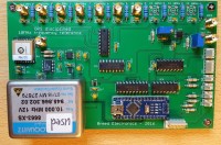
PCB
The main board contains several SMD components. I used my home made SMD oven to solder these on the board. A heat gun will also work. With some patience it will also be able to solder the components on the pcb with a solder iron with thin point. The temperature sensor is placed underneath the OXCO. I used some heat conducting paste to make an optional thermal connection between the two. Just be sure to solder the SMD components before soldering the other components. All high frequency connectors are SMA type connectors. I like to use BNC connectors on the outside of the case, so I bought SMA to BNC converter cables. The BNC side is screwed on the front and back panel of the case.
Software
When the Arduino is started it will wait until the OCXO has reached the desired temperature and the GPS has at least 3 fixes. Because warming up takes about 15 minutes the GPS will normally have more than 3 at the time the desired temperature has been reached.
The Arduino will start the measurement with a 10s interval. Then it will set the DAC to the calculated voltage to correct the frequency. The accuracy of the output frequency will be 0.1Hz at this time. After that a measurement interval of 100s is taken and after that 1000s will be taken to get a 1mHz accurate measurement. When the measured frequency is less than 0.005Hz of the desired frequency of 10MHz the system is considered LOCKED. It will repeat the 1000s interval measurements. Taking 1000s intervals will also eliminate the jitter of the 1PPS signal. It will take about 20 minutes to get to a LOCKED status from the start of the measurements after warming up for about 15 minutes.
Signals
See the logic analyser output for this explanation. The Arduino is setting CAPTURE high during the ISR just after receiving the 1PPS signal (1). At the next 1PPS positive edge the CCLR is set to high by the flip-flop (2), enabling the counter. On each rising edge of the 1PPS signal the current counted value is stored to a register of the counter. After 10 seconds the last stored value is read by the Arduino during the ISR and CAPTURE is set to low (3). This will clear the counter on the next 1PPS rising edge (4). This sequence is then repeated with an interval of 100 seconds and 1000s after that.
Measurement
I do not have any calibrated equipment. The only two ways I could check if the reference is working as expected was using a logic analyser and count the amount of rising edges between two 1PPS pulses. The other measurement I did was measuring the 10kHz output of a Navman Jupiter GPS with my frequency meter. The frequency reference was connected to the 10MHz reference input of the frequency meter. Both measurements were spot on, as expected. I attached the output of those as images to this article. I hope to come across someone here in the Netherlands who has a calibrated frequency meter to do some further checking.
I own some frequency counters and signal generators, but when measuring one with another they do not show the same frequency on their display. The do not seem to be very accurate, all of them have normal crystals as their reference. But some of them have a 10MHz reference input at the back. So creating a 10MHz reference solves that problem.
Some people buy a 10MHz Rb-reference, but that device also has to be calibrated and it is also quite expensive, around $200,-. Another problem I have is that I do not own any calibrated frequency counter, therefore I am not able to calibrate it. So I need a reference which calibrates itself.
There are a lot of old 10MHz oven controlled oscillators on ebay for around $20,-, they come from old GSM stations but work just fine for our purpose. So I bought one and started this project on a breadboard. I will use the GPS system to calibrate the oscillator with a 0.005 Hz accuracy.
There are a lot of these kind of projects on the internet. Some of them use a pll, but those take days to calibrate. Most of those projects use a GPS receiver with a 10kHz output as a reference for the PLL. But these GPS receivers are not very common anymore and if you can get hold of one it will be an old one which is less accurate then todays GPS receivers. The GPS receiver I use is a GlobalTop FGPMMOPA6H. It is cheap and has a 1 PPS (Pulse per second) output with less than 10ns jitter. But a 1 Hz output cannot be used together with the PLL method, so I will have to count the amount of rising edges of the oscillator which occur within a certain timespan instead. The long term stability of the OCXO I got is 2x10E-10/day and the short term stability (Allen variance) < 10E-11. The reference should get the same specs after it has successfully calibrated itself.
Features
- 4x 10MHz outputs
- 2x 5MHz outputs
- 2x 1MHz outputs
- 2 Hz output
- 1 PPS output
- 2x20 LCD
- short calibration time
- 0.005 Hz accuracy
OCXO Measurements
I did some measurements on the Oscilloquartz 8663-XS OXCO I use. Here are the results.
Current draw @ 12V:
measured: I(cold) = 490mA datasheet: <8W --> I(cold) <666mA
measured: I(warm) = 200mA datasheet: <2.5W --> I(warm) <208mA
Uout = 2,12Vpp sinewave datasheet: >+4dBm / 50 Ohm
Frequency control:
Voltage range: 0-10V
f(0v) = 10000091.5 Hz
f(10V) = 10000099.0 Hz
measured: Δf = 7.5 Hz datasheet: > 3Hz
Schematics
The project contains to schematics and PCBs. One is the main board and the other the power supply.
The power supply generates a 12V, 5V and 3.3V output. The 3.3V output is for the GPS, the 12V for the OCXO the 5V is for the rest of the components.
The OCXO Q1 is on the main board and is the oven controlled oscillator. It works on 12V and will consume about 7W when warming up to about 50 Celsius. After that it will consume less than 2.5W. Before the actual frequency measurements can start the OCXO has to be at the right temperature. The temperature is being measured by U1, a TMP 100 I2C temperature sensor. The sensor is a smd device which is placed underneath the OCXO to get an accurate temperature reading. The counting is started when the temperature is above 45 Celsius and if it has not risen for 30 seconds. The OCXO is wrapped with some insulation to minimize temperature changes. The temperature reached when warmed up is around 55 Celsius.
The output of the OCXO is a 2Vpp sine wave and is converted to a square wave by a high speed comparator (U6). The output of the comparator is divided by 2 and then by 5 by 2 4-bit decade counters (IC5) to get a 5MHz and a 1MHz signal. If you do not need those you can remove IC5 and X8-X11 together with their accompanied capacitors and resistors to save some money. All the signals are buffered by a MC3487 line driver and are terminated with a 100nF capacitor to 50Ohm resistor to get the correct output impedance and to keep any DC from entering the line driver.
The 10MHz signal from the comparator is also fed into U7, a 32 bit counter. U7 will count the amount of rising edges between a certain amount of 1PPS pulses from the GPS module (U2). To get the desired accuracy the counter has to start and stop counting exactly on the 1 PPS rising edges. This is being done with the help of the D-type flip-flop IC4. The Arduino requests a new measurement by setting the CAPTURE signal high. The next rising edge of the 1PPS signal, which is connected to the CLK of the flip-flop, will start the actual counting of the 10MHz signal by making ~CCLR of U7 high. Every 1PPS pulse is also used to execute a ISR by the Arduino. It keeps track of the amount of 1PPS signals there has been since the counting started. When the desired amount of 1PPS signals has reached the counter is being read by the Arduino and the CAPTURE signal is set to low to clear the counter on the next 1pps pulse. The 1PPS signal is also attached to the RCLK input of the counter. A rising edge on RCLK will copy the current counter value to a register. This register will not change until the next rising edge on RCLK so the Arduino has 1s to read the counter register until it changes again. The counter has an 8 bit output (Y0-Y7), so 4 bytes has to be read to get the 32 bit value. The byte to read can be selected using the ~GAL, ~GAU, ~GBL and ~GBU signals.
When the Arduino has read the counted value it can calculate the difference between the desired and the measured count. It will set the voltage of a 12 bit DAC (U4) with I2C interface to adjust the OCXO output frequency. U3 is used to convert the 0 - 4.095V output of the DAC to 0 – 10V which is the input range of the OCXO adjustment pin. The DAC uses an very accurate low noise voltage reference REF5040 instead of its own internal reference. The frequency resolution is 7.5Hz / 4096 = 0.0018Hz.
IC4B is used to generate a 2Hz signal with a 50% duty cycle out of the 1PPS signal. U9 is used to buffer the 1PPS, 2Hz and GPS serial interface. It is also used to drive the 2Hz and Locked LEDs.
Since the Arduino Nano has limited output pins the LCD display is connected through a I2C interface. R8 and R9 are pull up resistors required by the I2C bus.
PCB
The main board contains several SMD components. I used my home made SMD oven to solder these on the board. A heat gun will also work. With some patience it will also be able to solder the components on the pcb with a solder iron with thin point. The temperature sensor is placed underneath the OXCO. I used some heat conducting paste to make an optional thermal connection between the two. Just be sure to solder the SMD components before soldering the other components. All high frequency connectors are SMA type connectors. I like to use BNC connectors on the outside of the case, so I bought SMA to BNC converter cables. The BNC side is screwed on the front and back panel of the case.
Software
When the Arduino is started it will wait until the OCXO has reached the desired temperature and the GPS has at least 3 fixes. Because warming up takes about 15 minutes the GPS will normally have more than 3 at the time the desired temperature has been reached.
The Arduino will start the measurement with a 10s interval. Then it will set the DAC to the calculated voltage to correct the frequency. The accuracy of the output frequency will be 0.1Hz at this time. After that a measurement interval of 100s is taken and after that 1000s will be taken to get a 1mHz accurate measurement. When the measured frequency is less than 0.005Hz of the desired frequency of 10MHz the system is considered LOCKED. It will repeat the 1000s interval measurements. Taking 1000s intervals will also eliminate the jitter of the 1PPS signal. It will take about 20 minutes to get to a LOCKED status from the start of the measurements after warming up for about 15 minutes.
Signals
See the logic analyser output for this explanation. The Arduino is setting CAPTURE high during the ISR just after receiving the 1PPS signal (1). At the next 1PPS positive edge the CCLR is set to high by the flip-flop (2), enabling the counter. On each rising edge of the 1PPS signal the current counted value is stored to a register of the counter. After 10 seconds the last stored value is read by the Arduino during the ISR and CAPTURE is set to low (3). This will clear the counter on the next 1PPS rising edge (4). This sequence is then repeated with an interval of 100 seconds and 1000s after that.
Measurement
I do not have any calibrated equipment. The only two ways I could check if the reference is working as expected was using a logic analyser and count the amount of rising edges between two 1PPS pulses. The other measurement I did was measuring the 10kHz output of a Navman Jupiter GPS with my frequency meter. The frequency reference was connected to the 10MHz reference input of the frequency meter. Both measurements were spot on, as expected. I attached the output of those as images to this article. I hope to come across someone here in the Netherlands who has a calibrated frequency meter to do some further checking.
Updates from the author