

High-end propeller clock [120732]
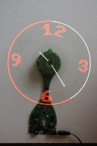
Buy it here!A propeller clock, also known as a Persistance Of Vision (POV) display is based on a mechanically moving led row. This led row is either oscillating or rotating at a rate superior to human's eye remanence, making a dot matrix which seems to float in the air.
A propeller clock, also known as a Persistance Of Vision (POV) display is based on a mechanically moving led row. This led row is either oscillating or rotating at a rate superior to human's eye remanence, making a dot matrix which seems to float in the air.
I've already built two of them, but they were only prototypes used to validate some technical solutions. Now I want to concretise these two tries into a fully fonctionnal system, which I could use in my living room 24h/24. To attain this goal, the system has to be silent and not subject to wear.
You'll find many similar projects on the web, but many of them are only table prototypes. I want to overtake this status and design a high-end system. But of course, the system has to be feasible by the most of us even with limited mechanical tools or skills.
The design is based on a hard disk drive brushless motor. Those parts are designed to be really silent and able to run for long periods.
The rotating board is a 20cm long 2-blades propeller, each of them containing 25 bicolor leds. This design has the advantage of beeing naturally balanced and offering a double refresh rate. On my previous prototype, i found that the propeller had to run at more than 3000t/min to offer a sufficient refresh rate, but this made air noise. With this double refresh, I'll be able to reduce at only 1500t/min without any flickering effect. The propeller contains 2 infrared sensors at each extremity to give a mechanical position reference. This propeller is then able to display a 25*128 dot bicolor round matrix.
The question of powering this rotating part is a big deal on those kind of systems. Some of them use batteries (no for me, thanks) or rotating brushes, which are of course incompatible with wear and noise requirements. On my previous system, I used a rotating transformer design wich worked great ! The secondary is wound on the motor's hub, rotating with it. The primary is wound a bit larger, but is static. This rotating transformer is then used in a simple flyback power supply... The power transmitted is enough to power all leds, even if efficiency is a bit weak... For this design I plan tu use a push-pull transformer, more stable in an open loop regulation. I guess winding a transformer could frigthen some of you, but I managed to do this, you'll be able too ! It only needs patience, adhesive tape and cyanoacrylate glue...
Some of similar projects embbed the Real Time clock on the rotating part... But this is a bit tricky when you need to set it up. To answer the noiseless requirement, I think the rotating part has to be lighter as possible, so I chose to let most of parts on static board, such as RTC, switches... The base board will be responsible of powering the motor, driving the transformer, keeping time and... telling the propeller what to display... To communicate between the base board and the rotating one, I succesfully used an infrared transmission with a phototransistor rotating with the propeller just above an 9 infrared led circle.
Update 14/11/2012 : Transformer winding
I've spent my last evening winding the secondary of the rotating transformer on the rotor of the brushless motor. I used 0.56mm enamelled copper wire. I was able to make 10 turns on first layer and 9 on the second one. Those 19 turns form one half of the secondary, 19 more turns needs to be added to complete the winding... But finally, instead of using two secondaries, i will only use this one on the push-pull converter and use a full diode bridge to redress output voltage. Simulation is still ok, showing a 18V voltage at low load and falling to about 8V with 3.5W load. That's more than needed...
I also made power estimation... I realised i forgot the snubber circuit for the mosfets. Even if currents are weak, the added snubber significantly reduces power loss in the transistors...
I finally added a small current monitoring resistor in series with one of the mosfets, it will help to visualise switching current during tests.
Photos of the transformer coming soon...
Update 21/11/2012 : Processing layout
After loosing a lot of work due to a problem with an USB Drive, I finally managed to complete layout (but transformer pictures have been lost. I'll took some more as possible).
As you'll see on the corresponding picture, I've added some useful details :
Update 12/12/2012 : PCB received
I've finally received my new circuits boards. They have been realised by Eurocircuits, it was the first time for me. I used to have them manufactured by futurlec previsously. Eurocircuits is a bit more expensive but realisation and transport delay is far more interesting.
I've started to solder power supplies, and already found some mistakes which will have to be corrected in next revision. Soldering needs to be patient because of the full SMD realisation and the fact that I used 0805 chips for place constraints. Furthermore, the 50 bicolor leds soldering needs to be as perfect as possible. A small misalignment will be visible while running.I'm satisfied with the "Power SO8" soldering as discussed previously, the 3mm hole under the chip easily allows power pad soldering.
I'm currently working on Propeller software writing. The display code is almost done. Now the big part is to implement the serial communication protocol between Base and Propeller...
Update 13/12/2012 : Photos updated
As promised, here are a few pictures of the new propeller and transformer.
The transformer is winded around the motor's rotor. Turns are glued with cyanoacrylate during winding process, and will then be covered with a thin layer of epoxy glue. The secondary is made of 0.56mm copper wire. 2 layers are winded, with 10 turns on the first layer and 9 turns on the second one.
The primary is then winded around the secondary, using a small circle of cardboard. This cardboard should ideally be the thinnest as possible, but keep in mind it must provide sufficient gap when removed to allow rotation of the secondary within this primary.
There are to primaries. The first one is made in the same maneer as the secondary : 2 layers of 10 + 10 turns, the transformer center point is then taken out, and winding process continues with the second primary, with exactly the same characteristics. While the winding is completed, a thin layer of epoxy is applied on the outer layer to add strengh.
I agree that's the tricky operation of this project, but the rotating transformer and the contactless energy transmission is far more interesting than a pair of brushes...
Theorically, with this construction, each primary should be around 18µH. I'll try to measure it at work...
Update 13/12/2012, a bit later :
I found an old network analyser at work to measure my transformer. At first I was quite happy, each primary gave 23µH... but this was primary only. I then tried to measure with the secondary + the motor inside the primary, and found only 9µH !
With U = Ldi/dt, we find that a 9µH powered by 9v gives a current ramp of 1A/µs. The mosfets driving the transformer are given for 2A max, so I need to switch at a frequency of about 500kHz... way too much !
I'll have to wind it again, I'll try with a 0.4mm wire with more turns...
Update 03/01/2013, A few issues encountered, on the way to improve transformer :
As I told previously, I tried to wind a new transformer with 0.4mm wire instead of 0.56. I managed to wind 2x27turns on primary and 33 turns on secondary. I then measured a primary inductance around 25µH which is acceptable with a switching frequency of 100k to 200kHz.
However, first runs with this transformer weren't as good as I expected. I only had a few volts on secondary (around 3.5V). Simulation told me it should be around 7.5V with load connected and 18V without.
After spending christmas holidays thinking to this problem, I see 3 possible explanations to this :
1 -The aluminium casing of the motor captures a big part of magnetical field, acting like a short circuited turn.
2 - Although mosfets (FDC6561N) are specified for a 3V Vgs, their gate driving is to weak (driven directly by a microcontroller's output). Simulation confirms this hypothesis
3 - Magnetic coupling of the transformer is too weak. My previous propeller clock used more turns (around 130 on primary and 180 on secondary)
I'm on the way to experiment a new design :
- Add a totem pole driving between the microcontroller's output and mosfet's gate
- Change mosfet to an IRLML0060 which can handle a higher Vds voltage (oscilloscope captures shows a peak voltage of around 80V on transistor opening without any snubber, and 30V with snubber connected)
- Wind a new transformer. This time, it'll be wound on a 32mm PVC pipe to add some distance with the motor's aluminium core, and allow a few more turns
I'll keep you in touch...
Update 08/01/2013, Motor issue:
I've assembled the propeller on the motor's hub for the first time, but it's a disappointing experience. With no load, motor runs very smoothly without any noise, but with the propeller, it does not manage to start. Sensorless brushless motors have a particuliar startup procedure which fails with the MTD6501. I guess the "locked rotor protection" activates because of the high inertia moment of the rotating assembly. I tried to fool the controller by adding a few ohms on motor's wires but it doesn't solve the problem.
I wanted to use this HDD brushless motor because of its quality and it's no noise running, but I have to reconsider the problem: I am going to replace it by a fan motor, driven with a DC voltage. Hopefully, I've found a good one at work, on ball bearings, which tends to be rare nowadays. Furthermore, it seems to have a hub diameter compatible with the transformer I wound, will check this evening...
Finally, using a fan motor will be easier to find than a HDD one for other peaople who wants to try this project !
Update 09/01/2013, Transformer works!
Yeah ! After 5 evenings of windings many transformers, this one is the good one !
The driver circuit has been ruggedized, aluminium hdd motor has been thrown out and replaced by a 92mm fan motor. I improved the snubber circuit to attenuate some high voltage spikes.
The transformer now works at 50kHz, due to its increased inductance, but this is easier to avoid ringing issues.
I measured an output voltage aroung 12V even when heavily loaded (20 leds lit at maximum power). I did not tried to measure output power, it's just sufficient for the needs I have.
This is the first 'magical' step of the project. With base powered, it so magical to just approach the propeller and see it illuminating without any wire !
Furthermore, infrared transmission perfectly works too, which is helpful to debug. Next step : new motor mounting...
Update 03/03/2013, Demonstration video online!
The hardware is now 100% validated, the big part now is completing the software.
I am currently working on propeller's code, serial frames processing, different types of display, color management, numerical/analog display format.
Have a look at the small demonstration video : http://youtu.be/CVzaX0vt5qg
Update 27/05/2013, Software completed, new video online!
The software is finally completed. Discover all the propeller's clock features on the video : http://youtu.be/wGTFo2QSqzo
Update 21/04/2015, Mechanical assembly, some people interested?
My boss asked me to design a mechanical assembly to cover the Clock and give it a more "finished" appearance. A friend of mine works in a laser-cutting company so I enjoyed myself in the drawing (See project's pictures)
The blades are covered by two acrylic disks to minimise collision risks.
If you like those mechanical parts, we could work together to offer an updtae package to clock enthusiasts ?
Update 19/11/2015: New software, Version E
Discussion (18 comments)
Alfredo Pérez 4 years ago
gracias por la respuesta estoy seguro que me ayudaran para salir de las dudas
dan ocho 5 years ago
dan ocho 6 years ago
for your answers thus far.
[Here, there is an attached .png to view]
Looking at the front of the PCB, propeller is lower and the base is upper. There are 50 sets of four lands for diodes (D1-D50), right?
Negative on the LED goes to the upper right.
True or False; and if False which way does it point?
Tnks,
Dan O.
dan ocho 5 years ago
am I able to program the UltiProp clock's
propeller and base using ISP pins (J2,
J3) by way of an arduino uno and it's ICSP cluster..
I am thinking:
Use the link on Elektor page.
Take your software and create a sketch
with ArduinoAVR in the IDE, and upload the
sketch over to the base and prop.
Or any suggestion?
Thanks in advance for your tim-e- & consideration
Dan O.
dan ocho 6 years ago
PANEL DESIGNS were xcellently rendered.
Dan O.
tothnandor.eu@gmail.com 6 years ago
tothnandor.eu@gmail.com 6 years ago
top-bottom-pcb2.JPG (323kb)
Bobbylebob 6 years ago
dan ocho 6 years ago
Dan O.
dan ocho 6 years ago
I tried to wind the transformer with AWG24 (0.56mm as suggested in "building the transformer", from 2014) attempting the secondary (25-24-23-22) and the primary (26-25-26-25), I found my possible turns always less than these totals.
Now I see, in the comments to Whiskey Soda(?) suggestions to make the transformer using 0.4 mm enameled wire which is AWG26 and the turns for the secondary (20-19-20-19) and the primary turns as 23-22-23-22.
What diameter (in mm) enameled wire and how many turns?
I am hoping that you can "straighten me out" on the winding issue.
Dan O.
Bobbylebob 6 years ago
Dan,
In fact, the number of turns greatly depends on the motor height and it's not always possible to reach what i suggested in the article.
Do what you can, it will surely work as is. The peak to peak current will increase but there is enough margin to accomodate these values.
My first prototype was made of 0.4mm wire but we switched to thicker one to ease the winding process.
Have fun knitting ;-)
Gerrit D'hoossche 6 years ago
I made the transformer a few times. Not only for my clock, But also for friends. The first transformer i used 0,6 mm enamelled wire from velleman. A few turns more of less doesn’t seem to matter. Second time with enamelled wire 0,56 from Farnell. The same result. The clocks are working just fine. I would suggest not using the 0,4 wire and don’t worry about the number of turns. Greatings Gerrit from Belgium.
tothnandor.eu@gmail.com 6 years ago
tothnandor.eu@gmail.com 6 years ago
How to get such a functional propeller clock. How much is it? Where to order?
Bobbylebob 6 years ago
However, I think you can find free Gerber visualisation programs on the web which will allow you to print layers
tothnandor.eu@gmail.com 6 years ago
Bobbylebob 6 years ago
coleen hue 6 years ago
Personally, I am not an experienced electro-constructor. Have really only made a couple of LED kits to beef-up my soldering skills. When I saw the Ultiprop I knew I should try to build it and this is written as I await my Ultiprop Clock PCB & chips from Ekektor:
Will it be necessary to modify this design for allowance between mains current difference in US and Europe (i.e. 50Hz vs. 60Hz.)?
Excuse my ignorance by answering
While I Thank You
Dan O.
Bobbylebob 5 years ago
I sent you an e-mail a few days ago. Did you receive it?
ALFREDO Hp PEREZ 5 years ago
K. Horton ,
Cómo está Ud, tu versión de POV está muy bueno serias gentil de enviarme los archivos que necesitaste para construir tu versión, no te digo que me lo envies gratis. de eso nos podremos de acuerdo por interno, mi correo es alfredoperez8709@gmail.com estoy muy interesado en adquirir tus archivos.
espero pronta tu respuesta. saludos.
Bobbylebob 6 years ago
I'm very impressed by the improvements you did on this project! I only had feedbacks about people which stayed in the original design but never heard of work like yours. Congratulations for this !
The outer ring bicolor LED was very difficult to choose because only a few color combinations are available. Your solution overcomes this issue nicely.
My latest software revision is E and it is available at the bottom of this article. However, I'd be pleased if you could share yours. Besides the RGB modification, did you add some other improvements?
We told about the casing to get feedback about interested readers but that was not very successful. It is made of laser cut aluminum panels oven painted and milled plexiglas panels. As these are very low volume production, they are quite expensive. However, I have one set of parts laying in my workshop.
On the follwoing picture, the white paint over the front acrylic plate has been replaced by a grey vinyl adhesive which looks better.
Please contact me in private (ardouin.david.projects@gmail.com) if you're interested.
Thank you very much for your feedback :-)
.David.
K. Horton 6 years ago
I made my own PCB’s and made a number of changes to the hardware and software, most notably replacing the outer ring LEDS with tri-colour ones to give a multi-colour outer ring. I also changed the outer ring patterns and improved the menus to give more consistent choice of colour schemes.
Incidentally, Elektor said some time ago that updated software was available, but this never materialised. I think there was also talk of some sort of case, but again it didn’t materialise!
As already mentioned, the clock works off a 12 volt DC ‘wall plug’ power supply, so it does not matter whether you have 50 or 60 Hz mains or 110 / 230-volt supply (providing your plug-in power supply is compatible). Time keeping comes from a real-time clock on the stator board with ‘memory’ capacitor backup for power downs.
Although the U10, stator microcontroller is no longer available from Elektor, it is easy (and cheaper) to program your own (and the rotor one as well). Download the trial version of the IAR embedded workbench for Atmel AVR and program the microcontroller with eXtreme burner – AVR. The trial only lasts a month, so you will have to complete your programming within this time.
Although it is quite possible to construct the clock using basic tools and a very fine tipped soldering iron, you need to be aware that this is an extremely advanced project with mainly surface amount components. It would be wise to practice on a cheap surface mount project first (or some scrap components) to ‘get your hand in’ The two microcontrollers are probably the most challenging so if you can manage those you are probably going to be OK.
Ken
PS Sorry, not the best pictures inthe world!
img-20190105-172957569.jpg (282kb)
Alfredo Pérez 4 years ago
K. Horton 4 years ago
Your first step is to design and make a replacement propeller PCB.
I could not find an easy was of modifying the original PCB, but you could possibly tweak the original artwork.
The changes are as follows:
Delete D25 and D50 the outermost bi-colour LEDS and replace them with tri-colour LEDS. These are connected as follows:
D25 Red to U2 pin 30 (P5) was bi-colour LED red
D25 Blue to U2 pin 7 (P9) was bi-colour LED yellow
D25 Green to U2 pin 6 (P12) was spare unused pin
Connect D50 similarly to U4.
I found the tri-coloured LEDS that I used much brighter than the bi-colour LEDS and used the low-tech solution of gluing small pieces of paper over the lenses (which worked very well), but a much better solution would be to incorporate current limiting resistors between U2/4 and the tri-colour LEDs.
Once you have made the new PCB, I can send you a copy of my revised software subject to the original author's permission.
Note that I have made many tweaks and changes to both the original base and propeller software and it would be provided as is, without warranty, and I am not able to provide any sort of help, guidance or support.
Regards
K Horton
PS I should have mentioned that there is no reason why this software should not work with the original hardware, but obviously my green will appear blank and if using the original LEDs, my blue will be yellow!
Alfredo Pérez 4 years ago
K. Horton 4 years ago
I am concerned that you say you are not an expert in electronics. This is an extremely advanced project and requires skill in assembling surface mount components.
Alfredo Pérez 4 years ago
K. Horton 4 years ago
I have made several modifications for my own personal use and make them available for individual amateur use and NOT for commercial use or profit. The modifications are provided as is, without warranty and I am unable to offer any form of help, advice, or support. Many of the changes are marked with my initials: KFH.
The main modifications I have made (as far as I can remember) are for the support the outer RGB LEDs and changes to the colour schemes and outer ring patterns to suit. Propeller stability improvements and a ‘focus’ facility to synchronise the two propeller blades. These may (or may not) improve things in general but work well with my propeller. Watchdog code for the base. Different remote-control codes.
Changes to the propeller circuit have already been noted, and I do not think there were any changes to the base hardware.
PS I should have mentioned that there is no reason why this software should not work with the original hardware, but obviously my green will appear blank and if using the original LEDs, my blue will be yellow!
Bobbylebob 4 years ago
Alfredo Pérez 4 years ago
K. Horton 4 years ago
Bobbylebob 6 years ago
Thank you very much for your comments, it is always pleasant to read from electronics lovers :-)
I see that U10, stator microcontroller, is no longer available on Elektor's store. Were you lucky enough to get the last one ?
As the clock is supplied by a 12Vdc voltage from a wall adapter, you will not have anything to modifiy on the clock itself. Just use a 12V / 1A adapter corresponding to US standard.
Don't hesitate to contact me if you need building advices, it's been a while since I last discuss about this project.
Best regards,
.David.
ALFREDO Hp PEREZ 6 years ago
MAS BIEN QUISIERA HACERLOS UNA PREGUNTA EL MAX DS3231 POR QUE NO LLEVA UNA BATERIA SI TODOS SABEMOS QUE NO RELOJ UN TIEMPO REAL LLEVA UNA BATERIA PARA QUE NO PIERDA SU CONFIGURACION DE LA HORA. ESPERO SUS RESPUESTA PRONTA. SALUDOS CORDIALES.
mkstevo 9 years ago
Would the plexi-glass enclosure pick up a lot of dust? I have to dust my clock around once a month as it collects a layer of dust on the forward edges of the propellor arms as it rotates. If the enclosure has full sides then this should prevent the dust from being picked up, if there are no edges I fear it may soon look 'dirty' inside and lose the Wife Acceptance Factor.
whiskey Soda 10 years ago
Finely I have time to build this Clock
Now i run into some problems. can you help me?
I finished the propellor, my programmer want a .hex file. in the files I find I an .a90 file this looks like a hex file. Can I yust rename this file to .HEX and program it?
In my fuse settings I can select 'divide internely by 8' this is standard yes in my programmer. Is this correct
It woeld be very helpfull if the micro dont see comunication and dont see rotation pulses. it start a test program: lighting all te led's one by one (in two colars) to test the board.
Please give me your e-mail adres to comunicate faster
wim_sanders@upcmail.nl
Bobbylebob 10 years ago
ClemensValens 10 years ago
ebab 10 years ago
Hi,
First of all, excellent project, simply outstanding.
I just finished assembling it. Works like a charm. Due to probably not centering
perfectly the propeller a horizontal vibration is noticeable. I'm afraid that will work against lifetime of the fan bearings. I'm trying to figure out on which end to put on solder blobs in order to at least diminish the vibration, no success so far. Whatever amount of solder I put on side, the vibration stays unaffected in amplitude. There is no effect when manually turn the propeller. Both tips rise up to same height when checked visually against a backround, neither end has a tendency to end up at the bottom.
Out of your experience with the prototypes, did occur a trick to you to identify the end where more mass is required and what could be the weight to put on?
Christoph 10 years ago
Hi
My propeller wobbels a bit because I did not mount the propeller exactly parallel to the motor surface (thickness of glue is probably not constant). This means that the leds of the two blades are not at the same location when turning round. As the location is a time variable, could this be corrected by software, with a software 'potentiometer'? The radial distance from the center should also be a parameter.
Thank you for this funny sophisticated project!
JohnHind 11 years ago
Just read the first installment in the magazine - cool project, congratulations!
One possible improvement occured to me though: did you think of, or experiment with, interlacing the pixels? If you offset the pixels on one propeller blade by half the pixel pitch, in theory you could get twice the annular resolution with the same perceived refresh rate. Additionally, this would probably fill the gaps between the pixels which are clearly visible in your video and photos.
This concept is somewhat similar to interlaced scanning in TV broadcasting so the perceptual theory is well proven.
Bobbylebob 11 years ago
rjv 11 years ago
Hi Folk,s
I just finished soldering 95% of the components on the pcb of the 120732 propellor clock.
Just a few more components, and then the question motor/transformer.!
Look at the picture i took. Also have a look at the video.
Bobbylebob 11 years ago
Mark1976 11 years ago
Bobbylebob 11 years ago
GuusAssmann 11 years ago
It has already been stated.
But there has been a complete project like this before. It consisted of a base station and a rotating part. And it had the same kind of transformer setup. It could be set, using an infra-red remote controll from a television set.
If anyone wants the data, I have it available.
And it includes complete PCB designs as well.
Bobbylebob 11 years ago
VinayDand 11 years ago
whiskey Soda 11 years ago
Can you please tell me what transformer you used now?
Nr of windings wire detentions etc?
Please update some documentation and pictures. Specially from motor and coil
I’m starting my own design now with KINGBRIGHT KAA-3528EMBSGC RGB leds and TEXAS INSTRUMENTS TLC5952DAP. I think I can learn (use) a lot from your design
Bobbylebob 12 years ago
whiskey Soda 12 years ago
Bobbylebob 12 years ago
rjv 11 years ago
This is a very nice project, in fact a friend of mine worked on a similiar pov clock.
We used a simple brushles motorcontroller for rc equipment to drive the brushles motor for the clock.
it started smoothly, even with load on it.
maybe this is an option for you?
Bobbylebob 12 years ago
whiskey Soda 11 years ago
Why you don’t use a motor from scale models.
Hobby king sell a lot of these motors all over the world.
From very small to very big. I use them for my quad copter.
You can buy also a controller, or build by your selves. If you buy a controller, this is controlled by 5 v pulses like as servo
http://www.hobbyking.com/hobbyking/store/__518__517__Electric_Motors-Micro_Profile.html
motor-2.png (75kb)
Bobbylebob 12 years ago
whiskey Soda 12 years ago
Bobbylebob 12 years ago
ClemensValens 11 years ago
Very interesting design, Bobbylebob. Excellent!
Will a hard-disk drive motor be strong enough to keep this working for months? Or days? How does the weight of the LED board compare to its normal load?
Regards,
Clemens
jerome 6 years ago
Ok pas de souci.
Oui plus facile en français.
Merci beaucoup.
Bobbylebob 6 years ago
Could we continue this discussion on my email adress : Ardouin.david.projects@gmail.com
It will be easier in French ????
jerome 6 years ago
Each time, i brase Q1 & Q2, maybe due to heat i break the net.
Here a video when i stop the propeller.
So when Q2 pass on D65 an other led switch ON and OFF when Q2 isn't align with D65.
When Q1 pass on D65 nothing happen, so that mean that there is a problem with Q1, isn't it?
Bobbylebob 6 years ago
Your video is very interesting.
First, camera's sensor is able to see the continous infrared flux emitted by D65. This is one good point and eliminates an potential issue.
Then, we can see all leds lighting in sequence, that's another good point but I had no doubt about this.
The interesting fact on your video is about the 2nd led (starting from the center). Normally, during test mode, it should only be activated when Q1 or Q2 sense D65 light. In your case, it's always activated! That means Q1 and/or Q2 are shorted to ground.
Please stop the propeller by hand during test mode. Do both n°2 Leds are always on ?
The one which is continuously lit shows the propeller side where the phototransistor is defective.
If both n°2 leds are activated, both Q1 and Q2 are shorted: maybe reversed?
Have a look on the enclosed TEMT1020 pinout. Emitter side ("E" pin) is connected to the GND copper plane of the propeller. Collector pin is connected to the thin net going to ATmega chip.
jerome 6 years ago
So i made a video, and all the led are working fine
Bobbylebob 6 years ago
At startup, both inner LED light up until first communication frame between base and propeller is received. In your case, one can clearly see those leds turning off as soon as D67 flashes once and frame is transmitted. This confirms that communication link is working, and U7 is OK.
Even if you already repaired Q1 and Q2, I suspect missing synchronisation pulse from them.
First easy test is to check if IR Led D65 works. After startup, if you look carefully in front of led die, you should see a very weak red color inside the led. If you are in doubt, the voltage between D65 pins should be around 1.5-2.0V. If voltage is close to 5V or 0V, D65 has failed.
The second interesting test is to start propeller in test mode. With power off, press rotating switch and hold it while plugging power then release it. The propeller starts to spin and all leds start turning on in sequence.
You should also see a static full radius from prop center to D65, confirming D65 to Q1/Q2 transmission works. You can even hold the propeller with you hand and slowly pass over D65 to confirm reception.
Please check these few steps and send a test mode video if needed.
jerome 6 years ago
The link of the video
Bobbylebob 10 years ago
jerome 10 years ago
Bobbylebob 10 years ago
jerome 10 years ago
jerome 11 years ago
Bobbylebob 11 years ago
jerome 11 years ago
Mark1976 11 years ago
SuperLabTV 11 years ago
Bobbylebob 12 years ago
VinayDand 12 years ago
VinayDand 12 years ago
Bobbylebob 12 years ago
whiskey Soda 12 years ago
Markus Barhofer 12 years ago
Bobbylebob 12 years ago