How to Make Design for Manufacturing Easy
on
Design for Manufacturing (DFM) offers decisive advantages: it reduces costs in prototype and series production, increases the quality and reliability of assemblies and conserves valuable resources. Eurocircuits freely available Visualizer makes DFM possible: fast, easy, and right first time.
When designing a PCB, the first thing that comes to mind is, of course, the electrical functionality. However, the PCB must be manufactured and populated with components and considered as early as possible in the design process. As most of the series production costs are determined during the prototype phase.
The layout of a PCB and which components are used helps determine the production cost and reliability of the hardware. Therefore, it is important to have a cost optimised prototype as it can easily be transferred to series production and thus fast entry of the product to the market.
Designers would greatly benefit by taking into consideration the realities of PCB manufacturing and assembly. A PCB is a very complex and technically demanding to manufacture as it is made of different materials and process steps with unavoidable manufacturing tolerances. An experienced PCB manufacturer knows how to manage these influencing factors and optimise their process. Nevertheless, industrial tolerances are reality and unavoidable.

An industrial-quality design Right First Time
When designing fault-free and reliable PCBs have knowledge of the manufacturing processes and their tolerances helps. Eurocircuits has packaged its manufacturing experience in their online engineering platform Visualizer. The Visualizer is a powerful tool for design review and verification. Available free of charge, in six languages and 24/7, Visualizer is also a user-friendly online ordering and price calculator. The platform was completely revised and further enhanced in 2020.
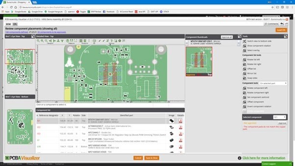
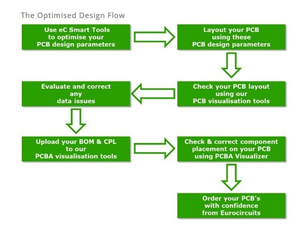
Interactive DFM tools for PCB production and assembly are integrated in the Visualizer to check the design data is complete, show critical points in the design and give concrete suggestions to correct design errors. The goal is always to suggest solutions where its alternative component parts or design changes to achieve a design that is suitable for manufacture.
The Visualizer works with over 700 rules to validate the parameter selected and has over 900 predefined build-ups for different PCB types. PCB designers also use the Visualizer to validate the data for assembling the PCB. For this purpose, the BOM and CPL can be uploaded, and the data validated. The central element is Eurocircuits database with over 250,000 electronic components.
The PCB and assembly are virtually manufactured in before ordering. This helps designers validate their design that is right the first time for manufacture - a validated parts list and component placement for assembly together with a 3D visualisation of the assembly. Validating the data/design shortens development times and makes it possible to optimally move prototypes into series production at any manufacturer.
https://www.eurocircuits.com


Discussion (0 comments)