

How to move from 8051 to ATMega (easily)
This project consists of a mezzanine that permits to use an ATMega DIL28 to replace a 8x51 (8751, 8951, RA2 ...) on a board.
I have many hardware (inside boxes) at home that perform home automation, they are most of them based on a old but very clever microcontroller (I mean the 8051). Of course I could redesign a new PCB to move to ATMega but as the analog sub systems work perfectly, I decided that replacing only the microcontroller is easier and quicker.
J'utilise à mon domicile plusieurs systèmes pour des fonctions domotiques au sens large. Ceux ci sont principalement basés sur un vieux mais très intelligent processeur (le 8051). Bien sur j'aurais pu re-concevoir une carte pour ATMega mais comme les parties électronqiues fonctionnent parfaitement, j'ai décidé que remplacer le microcontroleur était plus simple et plus rapide.
The 8051 has 32 I/Os (8 bits P0, P1, P2 and P3), but the ATMega has only 20 I/Os so I use a PCF8574 to get 8 more I/Os. As 20+8 means only 28, what about the 4 other pins ? Well first of all, if you decide to use the internal clock of the ATMega you can get 2 more I/Os.
In my case I modify a little bit the mother board to move the LCD connections from a 8 bits interface to a 4 bits interface.
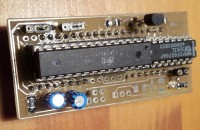
For this board you need only an ATMega (on the pic ATMega168), a PF8574 (A or not), a BC547 to invert the reset line and some resistors and caps (most hidden below the DILs).
The most interesting job is now to update your software ... do not hesitate to contact me about that.
J'utilise à mon domicile plusieurs systèmes pour des fonctions domotiques au sens large. Ceux ci sont principalement basés sur un vieux mais très intelligent processeur (le 8051). Bien sur j'aurais pu re-concevoir une carte pour ATMega mais comme les parties électronqiues fonctionnent parfaitement, j'ai décidé que remplacer le microcontroleur était plus simple et plus rapide.
The 8051 has 32 I/Os (8 bits P0, P1, P2 and P3), but the ATMega has only 20 I/Os so I use a PCF8574 to get 8 more I/Os. As 20+8 means only 28, what about the 4 other pins ? Well first of all, if you decide to use the internal clock of the ATMega you can get 2 more I/Os.
In my case I modify a little bit the mother board to move the LCD connections from a 8 bits interface to a 4 bits interface.
For this board you need only an ATMega (on the pic ATMega168), a PF8574 (A or not), a BC547 to invert the reset line and some resistors and caps (most hidden below the DILs).
The most interesting job is now to update your software ... do not hesitate to contact me about that.
Discussion (2 comments)

Epissure 6 years ago
Malheureusement, tout le monde n'a pas la chance de lire, de l'écrire, de comprendre l'anglais.
Alors que dans le monde, on parle le français dans de nomdreux pays.
Le français est la langue de la culture, venant du latin, je fais un constat, je ne dis pas que c'est mieux.
L'Anglais est la langue courante de tous les jours et la langue technique.
Par contre, entre le système métrique est bien plus simple que l'équivalent en unités impériales, à cause des décimales.
Au Royaume-Uni, l'usage du système métrique est obligatoire dans les domaines du commerce, de la santé publique, de la sécurité et de l'administration.
Je ne peux plus faire de voile, mais je reconnais dans la navigation aérienne et maritime, on utilise les unités impériales, mais cela provoque des erreurs quand on ne l'utilise pas tous les jours et on peut ne pas arriver ou être au bon endroit.
Je reconnais que les Anglais sont ennuyés quand il faut lire, écrire, comprendre, le français.
Pour ma part dans le monde de l'électronique, c'est l'Anglais qui pré-nomine donc complexe pour moi, mais je pense ne pas être seul, ou je suis la seule personne au monde qui est un idiot.
Pourtant, le Français aurait pu devenir la langue internationale, question d'histoire.
En France on ne doit plus depuis longtemps utiliser le Ch-eval pour déterminer une puissance, c'est le W-att qui doit être utilisé. Dans le domaine des moteurs thermiques on n'y arrivera pas. Les gens travaillant sur les moteurs électriques, en parlant de puissance utilisait le Ch-eval, quand vous sortez de l'école et dans les entreprises ils parlent en Ch-eval, moi, je n'en avais jamais entendu parler, je parlais en W-att. A une époque où il n'y a pas Internet, pour faire la différence et les bons calculs, j'ai eu du mal à trouver.
Je ne veux de mal à personne, mais c'est frustrant de ne rien à comprendre à l'anglais et à partir d'un certain âge très difficile de l'apprendre, j'ai essayé.
Reply

Show more
1 Comment(s)

Updates from the author
criki 9 years ago
- analyse your hardware and try to connect to PCF8574 only pin's that do not change so much. Most of the time it is ok because the P1 bus of the 8051 is the "only power" bus available so that it is often connected to outputs.
- then rewrite the low level functions to access your "old" hardware. On my side I rewrite the LCD interface, the keyboard interface, the I2C interface, the opto isolator command.
- then modify your timer functions, because even if you have the same number of timers in both microcontrollers, they do not operate exactly in the same ways.
- now migrate the rest of the software
- enjoy after check and test (as me) seeing your application running on AVR
- now the job is not fully finished because you have much more power available in the WVR so you can add functions, extensions, communications ... Good luck
criki 9 years ago
Concerning the prototype of the PCB
- at the top left corner you can identify 2 switches, they permits you to connect the crystal of the motherboard (generaly 12 MHz or 8 MHz) to the X1,X2 of the ATMega OR if you prefer to use X1 X2 of the ATMega as P2.0 and P2.1 of the 8051.
- top right is the BC547 for the reset line
- at the bottom right there are 2 pins, 1 is connected to the cathode of a Sot23 green led, 1 is connected to the INT of the PCF8574 so your software can be interrupted by a level change of one entry of the PCF.
Slightly left there is a MOSFET (not populated) that can switch the power of an external module (for instance to manage the backlight of an LCD)
and the last but the not the least there is a 6 pin connector (not populated) to feed the ATmega via an external programmer.