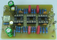
HQ PU RIAA PREAMP

Revive your vinyls
You might have an old Dual, Lenco, Thorens turntable, ... now is the time to bring it back to life with a guarantee of quality.
The diagram shown is taken from an old AN-124 application note from PMI Analog Devices around SSM2015. The latter being obsolete, I used a THAT1510.
The peculiarity of this assembly lies first in a pre-amplification before attacking the RIAA filter. Usually, a lot of PAs are built around a single operational amp (NE5534). As the noise level of the That 1510 is significantly lower, you will notice the difference. It will always be possible to modify the gain with the formula G = 1 + 10K / Rg
Each cell has its attributes and the level is sometimes very different. If one wants at That 1510, the gain resistance can be replaced by a fixed 100 ohm resistor in series with an adjustable 220 ohm. The gain will be variable from 30 to 40 dB.
The NE5532 of the filter and the output stage can be replaced by LM4562
Project Elements
Discussion (11 comments)

Marc Schwarzburg 3 years ago
I would suggest an output cap of 2uF (MKP or at least MKS) on the output in series.

Marc Schwarzburg 3 years ago
Its totally passive like the ones you find in the tube phono preamps from the 1960 but with low impedance since we use semiconductors here. You can expect lower phase shifts in the filter than in solutions within the Op Amp feedback loop as other companies did...
You should use 0.1 % metalfoil resistors and 1% mkp capacitors in the filter or you select them from the junkbox after measuring some parts to get the right values.
the network will be placed between the output of "that1510" Opamp and the following input of the output buffer stage.
For the that1510 gain resistor i would recommend an 22 Ohm and a switch for paralleling an 220 Ohms resistor.
So you can choose between MM or MC systems.
In every case you will need a super clean power supply with no ripple on the rails. (shunt regulator or simple dual battery setup)
ERRYSON 3 years ago
I see that this is a bit the principle adopted in the manual of LM4562 or LME49720.
lme49720.pdf (1847kb)

Marc Schwarzburg 3 years ago
Yes this is a proven solution for high end audiophile equipment. Some famous phono preamps are based on this principle. I´ve seen this in even 4K USD equipment because of the linearity of the implementation.
The deviation in the parts of LME49720 datasheet is to compensate the parameters of this particular opamp shown.
btw. this Opamp should be awesome. I should really check this device.
My 2nd opamp is an Burr Brown OPA134 and this is excellent too. Don´t forget to block the supply pins with 220nf foil and 470uF electrolyt caps in parallel - nearest to the chip.
I attached a example schematic I found last year somewhere , I forgot where... but had a hardcopy
ERRYSON 3 years ago
It is possible to reduce the low end of the audio spectrum by inserting a capacitor with RG That1510 (2200µF 6V3 Muse Nichicon or Elna style)
For the OPA2134, it is a good output circuit because I have seen in the past some diagrams associating with output transformers JT112 of Jensen.

Marc Schwarzburg 3 years ago
Output transformer with opamps ? why ? whats the reason for this ? you will lost bandwith with bass and treble (high tones) because of eddy current in the iron core. I think that is stupid except you will need a studio balanced / symetrical XLR output. btw a good Audiotransformer is expensive.
Club AC-News 3 years ago
The reviews are disappointing.
The author has at least created something as a basis for work.
This base is perhaps the beginning of a future evolution. Who asked the question? An achievement, in itself, is never finished and always evolves over time.
If that's not right for you, who's ready to step up and step up?
ERRYSON 3 years ago
You understand my approach because this U-shaped sheet is used to bring together the connections, the 2 L&R preamps, the buffered stereo RIAA filter, the +/- 15v power supply is separate.
I much prefer this way of working where no wires are in the air but solder. No way for this type of project to take a breadboard.

josephfeng 3 years ago
Back in those days, Telefunken 112AX7's had a reputation for the lowest noise. Nowadays, the criterion seems to be the most euphonious distortion.

Tony Casey 3 years ago
With an average moving magnet cartridge (1k5+680mH), the performance of the NE5534 is only about 1.5dB worse than a theoretical "noiseless" amplifier with DIN A weighting. Most of the noise comes from the source impedance rather than the opamp (unless you cool the cartridge to close to absolute zero, but then it wouldn't work).
It would only be worthwhile if you use a "high" output moving coil cartridge with a low impedance.

PicoPete 3 years ago
Chris-H 3 years ago
My RIAA circuit uses a lowpass filter first for the HF part of the curve, then the bass boost and LF rolloff are done in a second stage. This has the advantage that surface noise is significantly reduced, and scratches don't sound excessively loud! The original of this was built using the TL074, for use in a disco mixer. If it's wanted for audiophile use, you can apply any of the exotic low-noise op-amps.
I didn't bother with an MM pre-amp stage, because I haven't found any cartridge that comes close to the V15 or MC35C for broadcast use!


Updates from the author
ERRYSON 2 weeks ago
pcb-with-ne5532-only.JPG (261kb)
ERRYSON 2 years ago
pu-mag-47k.JPG (234kb)
ERRYSON 2 years ago
ERRYSON 3 years ago
ERRYSON 3 years ago
http://www.retronik.fr/revues/radio-plans/1984/RP441_08-1984.pdf