

Mains Power Driver by MCU DC or PWM
There are not so many projects on the web where you can drive a mains power using a TRIAC. This project can drive 2000 watt by a DC or PWM control.
There are not so many projects on the web where you can drive a mains power using a TRIAC. This project can drive 2000 watt by a DC or PWM control.
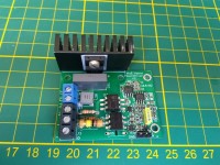
I did not want to use the MCU timers to control the 50Hz phase control. The setup also need to be able to drive inductive loads. So I defined a pulse driven solution controlled by a DC output or an PWM output of an MCU. The unit is perfectly running using a simple Arduino. Schematics, PCB and Arduino code is available. The picture is from a simple unit where an Arduino and all mains stuff is build in one box.
I am not sure whether mains connected projects are allowed here, so once I see people are interested I will publish more details.
Discussion (7 comments)


johns 7 years ago
I think you would be better using something like an H11AA! which is designed for the job. See attached data sheet.
Reply

TiemeKuyper 7 years ago
A capacitive coupling indeed is a no-go. The moment of zero crossing is important. A transformer without load, same story. Resistive detection is the only way. Both options do this. It depends of course if you care about this 0.5 watts additional. Anyway both solutions can be chosen.
Reply
TiemeKuyper 7 years ago
The load is 47kΩ on mains side, to drive the led in the optocoupler. I experimented with the value but for 110Vac surrounding this value is needed. It works till 260Vac but then dissipation increases. So about 0.3 watts is continuesly dissipated for 110V, 1.1 watt for 230V.
For 230V surrounding the input R may increase till 100kΩ, reducing to about 0.5 Watt
The original diagram has a negledgible dissipation.
For 230V surrounding the input R may increase till 100kΩ, reducing to about 0.5 Watt
The original diagram has a negledgible dissipation.
Reply
TiemeKuyper 7 years ago
Yes, that could be an option if you wish, but it uses somewhat more mains power which I thought not to be necessary. There are many ways to do this. See my comment on DanyR's remark, there I give a proposal to use the optical isolation. Note that the schematics needs every 0-crossing, to positive and negative going. Therefor the Exor is added there. It should work, I did not test it. But indeed the H11AA1 with the dual LED is also an option.
Reply
Show more
1 Attachment(s)
7 Comment(s)

Bob D Green 7 years ago
In general I like this project and I think it ciuld be useful. I would prefer to see an opto coupled zero crossing dtector. However, I do hope the project is formalized with a PCB and kit made available.
I think that the project notes have stimulated some very useful feedback.
I think that the project notes have stimulated some very useful feedback.
Reply

John Cronin 7 years ago
Agreed. They make modularized opto coupled solid state switches that are sealed in UL rated enclosures. Using them allows you to physically isolate the line power and improve the safety of your project. Done correctly using a good certified solid state switch "could" meet electrical codes. Putting a triac on a home made printed circuit will not meet electrical codes.
Reply
Show more
1 Comment(s)
Pizzakora 7 years ago
Tried a similar scheme some years ago for a commercial project to control a squirrel cage blower fan motor for aircon. The switching noise at low speed drove the customers crazy. Also precisely controlling some inductive loads at low speed proved more difficult than others. Good effort though.
Reply
Show more
0 Comment(s)

DanyR 7 years ago
Hi, I did not find a mains isolation component between the sections "mains in for 0 crossing" and "zero crossing detection".
R35 has a high value, but it provides no mains isolation...
Did I miss something?
Thanks in advance!
Very nice project by the way!
R35 has a high value, but it provides no mains isolation...
Did I miss something?
Thanks in advance!
Very nice project by the way!
Reply
TiemeKuyper 7 years ago
Indeed The combination 2x4M7+1M is not a full isolation, but in practice it is. Mains Isolation is always something discussable. In nearly all units there are decouple capacitors from the live & neutral to the cabinet ground causing a capacitive leak. This divider gives the exact 0-crossing in a simple and well working way.
Reply
Show more
2 Comment(s)
TiemeKuyper 7 years ago
Schematics in pdf added
Reply

TiemeKuyper 7 years ago
Indeed for a 3-phase surrounding this circuit is not suitable. This is also not a very common implementation. I think the wisest to do then is to use the regular optocoupler implementation as normally used. The 3n3's give here also a phase shift which you don't want. The disadavantage of the standard optocoupler is that it needs a dissipating series resistor.
I did a simulation with an optocoupler, and an exor at the output, which seems to be able to detect the both zero crossings. I am not able to test it here since our house only has 1 phase, but it should be able to do so. Will share the results later.
Added the drawing how it should work. Please realize that I have not tested this.
Reply
DanyR 7 years ago
Still one question about the 'mains in for 0 crossing' section: I assume that your mains voltage supply consists of one 'live' wire and one 'neutral' wire (marked 230VAC_L and 230VAC_N), where the level of the N wire is (approximately) the same as the one of the 'GND' connection of your circuit.
If so, everything works fine of course.
But, in some cases (as in my case) we have 2 live wires, and the actual mainsvoltage is if course the difference between the 2 voltages which have a mutual shift of 120 degrees. It is a 'star' configuration of the mains votage generators, where the 'star' point is the actual neutral wire (which is not available to us directly, but it is gronded). So, here the GND voltage is NOT connected to one of the mains wires.
This means the phase of the output voltage of the circuit is wrong with respect to the actual mains voltage.
See the added spice simulation.
Thanks in advance!
Reply
Show more
1 Attachment(s)
4 Comment(s)
Updates from the author
TiemeKuyper 7 years ago
I added a small YouTube movie to show how it is driving a 5 watt highly inductive fan to very low speeds: https://youtu.be/2q2jf5dnCzA
TiemeKuyper 7 years ago
TiemeKuyper 7 years ago
TiemeKuyper 6 years ago
TonGiesberts 5 years ago
TiemeKuyper 7 years ago
Note that there is no basic difference with the version shared earlier, using a high impedance resistor deviced to detect the 0-crossing of the mains sine wave. This version makes it fully isolated,
Drawback is that there is a continues load of 47kΩ. Which dissipates. When using it in a 230V surrounding this resistor can be increased to 100kΩ if you wish. Higher I would not recommend.
The actual results will be shared later on when I have a complete build-up.
TiemeKuyper 7 years ago
johns 7 years ago
It provides an easy way to interface any number of control functions to a mains driven device.
Keep up the good work.
John S.
John Cronin 7 years ago
https://www.opto22.com/documents/0859_Solid_State_Relays_data_sheet.pdf
You can put the relay/switch in a NEMA or IEC enclosure (junction box) and the rest of the electronics in its own separate enclosure.
TiemeKuyper 7 years ago
DanyR 7 years ago
I do not think this type of device is a replacement for a triac in this project. The triac ignition is phase controlled while the SSR are merely on/off state devices.
TiemeKuyper 7 years ago
Now update the schematics after checking with real components. To avoid confusion I removed the earlier version of schematics. It certainly needed some modifications
The one now attached works flawlessly from mains 65V till 260V, supply 1V7 till 5V5.
Later I will share the eagle files.
Update: I removed the schematics from here. The latest one is in the zip as posted on Feb28
NuttyProf 7 years ago
John Cronin 7 years ago
As I and other have stated, when creating electroncs to control AC Power (mains) best practice is to isoloate AC power and electronics that control it from the rest of the circuit. Opto-coupling is the best. Transformer coupling is good. No isolation is risky.
Good luck with your project!
TiemeKuyper 7 years ago
A power factor correction circuit is much more complex indeed.
Moonwalker 7 years ago
TiemeKuyper 7 years ago
Moonwalker 7 years ago
So by keeping the Triac biased until the wave reaches zero it would work properly on inductive loads? I am asking since I designed a simple dimmer but did not test on inductive loads yet.
TiemeKuyper 7 years ago
TiemeKuyper 7 years ago
TiemeKuyper 7 years ago
ClemensValens 7 years ago
TiemeKuyper 7 years ago
The Mains Power Driver is capable to be driven with a DC or PWM cntrolled signal.
Since the regulation is ratiometric, the driving is hardly supply dependant
The power supply of the circuit should be within 2.5 to 5.5V
It is a fully mains isolated circuit.
The circuit transforms the DC/PWM to a 50Hz synchronized pulse train
This pulse train keeps firing the Triac till the next Voltage zero crossing
The Current zero crossing of the Triac makes the non-conductive state for of the
4 quadrant Triac.
This principle makes the circuit capable of driving inductive loads like motors or
transformers, but of coarse also resistive lamps or heat elements.
The max current for the BT139 Triac depends very much on the heatsink applied
Since the BT139 has an isolated TO220 housing it should not be used above 5Amp
(1000W) with a small heatsink or 10Amp (2000W) with a proper heatsink
Basically the Mains Power Driver is controllable by a simple PWM or DC value
The analog circuit defines the timing, so no worries about MCU timers
The circuit inverts: Hi DC makes the mains fully blocked, 0 makes the mains fully conducted
An Arduino command analogWrite(PWMpin, PWMvalue); should fulfill to drive the input
A sketch is available showing a calculation based on a gamma compensation to recalculate a linear value to a brightness of an incandescent lamp where the human eye judges a linear control.
It is also applicable for motor controls, since there the lower speeds need more accurate control
TiemeKuyper 7 years ago
ClemensValens 7 years ago
From an isolation perspective, wouldn't it be better to route the TRIAC gate drive outside IC11 instead of under it? You have plenty of board space to do this.
TiemeKuyper 7 years ago