

Preamplifier 2012 (1) - introduction and line-in/tone/volume board (110650)
Audio lovers, sit up. Besides presenting a truly high end audio control preamplifier for home construction, this article series also aims to show how low-impedance design and multiple-amplifier techniques can be used to significantly reduce the noise levels in analogue circuitry.
Audio lovers, sit up. Besides presenting a truly high end audio control preamplifier for home construction, this article series also aims to show how low-impedance design and multiple-amplifier techniques can be used to significantly reduce the noise levels in analogue circuitry. The result of the design effort is a top-notch preamp that’s brilliant not just sonically but also in terms of cost/performance ratio.
Published in Elektor Magazine, no. 424, April 2012
By Douglas Self
It is now some time since I published a preamplifier design — the Precision Preamp in 1996. Inevitably technology has moved on. In that design the recording output level was as low as 150 mVrms to get a good disc input overload margin, the amplitude being well within the reach of the average tape recorder input level control. Nowadays most audio line inputs will be from digital sources, typically at 1 Vrms unbalanced or 2 Vrms balanced, and recognition of that requires a completely new design, especially in the MM/MC phono section.
The preamplifier described here demonstrates how very low noise levels can be achieved in analogue circuitry without using exotic parts. It was originally conceived as being entirely made up of 5532 opamps, like the earlier Elektor 5532 OpAmplifier but during the design process it became clear that adding a few LM4562s (which are now a good deal cheaper than they used to be) would avoid some awkward compromises on distortion performance, because of their superior load-driving ability.
In addition, the preamplifier has a very versatile MC/MM phono input stage with gain-switching, which I believe can optimally handle any cartridge on the market; this is guided by an innovative level indicator that provides more information than just on/off from one LED and does away with the need for bar-graph metering.
A block diagram of the proposed preamplifier is shown in Figure 1. In practice, the project is divided into several circuit boards, each of which will be discussed separately starting this month with the circuitry comprising the line amplifier, tone control, volume control, and output stage.
Noise of three kinds
There are three main causes of electronic noise in analogue circuitry: Johnson noise from resistors, and current and voltage noise from semiconductors.
All resistances (including those forming an integral part of other components, such as the base spreading resistance of a bipolar transistor) generate Johnson noise at a level that depends on the resistance and the absolute temperature. There is usually little you can do about the ambient temperature, but the resistance is under your control. Johnson noise can therefore be minimised by Low Impedance Design, in other words keeping the circuit impedances as low as possible.
In the early 1970s audio circuitry commonly used 25 kΩ or 50 kΩ potentiometers and associated components of proportionally high impedance, mainly because the discrete transistor circuitry of early opamps used had poor load-driving abilities. When the (NE)5532 appeared, and equally importantly, came down to a reasonable price, it was possible to reduce impedance levels and use 10 kΩ pots. This may not seem very ambitious when you consider that a 5532 can drive about 800 Ω while keeping its good distortion performance, but the pot value does not always give a good idea of, for example, the input impedance of the circuit block in which it is used. It is not widely known that a standard Baxandall tone control constructed with two 10 kΩ pots has an input impedance that can easily fall to less than 1 kΩ. There is a cunning way round this problem; the Bass and Treble tone control networks can be driven separately; more on this below.
Fixed resistors are available in almost any value, but the pot values available are much more restricted, and the lowest practical value, in that two-gang pots are available for stereo, is 1 kΩ.
Current noise is associated with opamp inputs. It only turns into voltage noise when it flows through an impedance, so it can be reduced by Low Impedance Design. The use of low value pots also means that opamp bias currents create less voltage drop in them and so there are less likely to be intrusive noises when the wiper is moved.
Voltage noise is the third type of noise. It is already in voltage format, being equivalent to a voltage noise generator in series with the opamp inputs, and so cannot be reduced by Low-Impedance Design. At first it seems that the only thing that can be done to minimise it to use the quietest opamps available. Opamps exist that are quieter than the 5532 or the LM4562, but they are expensive and have high current noise. A typical example is the AD797, which has the further drawback of only being available in a single package, putting the cost up more.
A better path is the powerful technique of using of multiple cheap amplifiers with their outputs summed — or to be more accurate, averaged. With two amplifiers connected in parallel, the signal gain is unchanged. Their outputs are averaged simply by connecting a low value resistance to each amplifier and taking the output from their junction. The two noise sources are uncorrelated, as they come from physically different components, so they partially cancel and the noise level drops by 3 dB(√2). The amplifier outputs are very nearly identical, so little current flows from one opamp to another and distortion is not compromised. The combining resistor values are so low (typically 10 Ω) that their Johnson noise is negligible. This strategy can be repeated by using four amplifiers, giving a signal-to-noise improvement of 6 dB, eight amplifiers give 9 dB, and so on. Obviously there are limits on how far you can take this sort of thing. Multiple opamps in parallel are also very useful for driving the low impedances of Low Impedance Design, so the two techniques work beautifully together. The Elektor 5532 OpAmplifier pretty much took this to its logical conclusion.
The multiple-amplifier approach gets unwieldy when the feedback components around each amplifier are expensive or over-numerous. To use two amplifiers in a standard Baxandall tone control you would have to use quad-gang rather than dual pots for stereo, and also duplicate all the resistors and capacitors. While this would reduce the effect of all the noise mechanisms in the circuit by √2, giving a solid 3 dB improvement, it is not an appealing scenario.
If instead you simply halved the impedance of the Baxandall network by halving the pot and resistance values and doubling the capacitor values, the situation is not equivalent. In the second case you have halved the effect of the opamp current noise flowing in the circuit impedances, and reduced the Johnson noise by root-two, but the opamp voltage noise remains unaffected and will often dominate.
Line input and balance control stage
This is a balanced input stage with gain variable over a limited range to implement the balance control function. Maximum gain is +3.7 dB and minimum gain –6.1 dB, which is more than enough for effective balance control. Gain with balance central is +0.2 dB.
Looking at the circuit diagram in Figure 2 and discussing the left (L) channel only,IC2A is the basic balanced amplifier; it is an LM4562 for low voltage noise and good driving ability. The resistances around it are low to reduce noise so it is fed by unity-gain buffers IC1A/B which give a high input impedance of 50 kΩ that improves the CMRR. Note the EMC filters R1-C1 and R2-C2 and the very start of the circuitry. The stage gain is set by 1 kΩ pot P1A, the negative feedback to IC2A being applied through two parallel unity-gain buffers IC3A/B so the variation in output impedance of the gain-control network will not degrade the CMRR. The dual buffers reduce noise and give also more drive capability. In this stage combining the buffer outputs is simple because the feedback resistance can be split into two halves; R8 and R9. This requires R11 and R12 to be paralleled to get exactly the right resistance value and so preserve the CMRR.
The noise output of this stage is very low: –109 dBu with the balance control central; –106 dBu at maximum gain and –116 dBu at minimum gain. (all 22 Hz – 22 kHz, rms)
The tone control stage
It is not obvious but this is (mostly) a conventional Baxandall tone-control. Once more 1 kΩ pots are used, requiring large capacitors to set the turnover frequencies, C7 at 1 μF sets the bass frequency and C8, C9 at 100 nF set the treble frequency. The cut/boost is ±10 dB maximum for both. The stage has a low input impedance, especially when set to boost; to deal with this the Bass and Treble parts of the tone-control network are driven separately. The Treble network C9-P3B-C8 is driven directly by IC2A in the previous stage, while the Bass network R15-C7-P2B-R14 is driven separately by the extra unity-gain buffer IC2B, the other half of the LM4562 in the line input stage. I call this a split-drive Baxandall circuit.
The Treble network is the two-capacitor version rather than the one-capacitor types; this has the advantage that the treble pot is uncoupled from the circuit at low frequencies and reduces the loading.
The main tone-control opamp is IC4A, which drives the Treble feedback path directly, while unity-gain buffer IC4B gives separate drive to the Bass feedback path. Polypropylene capacitors are strongly recommended as they are free from distortion while polyester types show significant non-linearity. Unfortunately they are also physically larger and more expensive, but well worth it in my view.
The noise output of the tone-control stage alone is only –113 dBu with controls set to flat.
Relays RE1 and REe2 implement a tone control defeat function by enabling the active volume control stage to be driven directly from IC2A. To prevent clicks and other noises when the relays switch over, R18 and R58 have been added, effectively keeping up the bias to IC9B and IC18A. To keep crosstalk down to a minimum each channel has its own relay. As a bonus, two contacts can be connected in parallel, preventing any risk of signal degradation and at the same time increasing life span.
Active volume control stage
The volume control is of the active Baxandall type which gives low noise at low volume settings and also synthesises a quasi-logarithmic control law from a linear pot, giving much superior channel balance. Maximum gain is +16 dB, with 0 dB obtained with the control central. The input impedance of the volume control stage, implemented with another 1 kΩpot P4A, falls to low values at high volume settings. It is therefore driven by the ‘load-splitting arrangement’ where buffer IC9B provides half of the drive from the tone-control stage. Resistors R19, R20 ensure that IC4A and IC9B share the load between them.
The conventional Baxandall active volume control as in [1] uses a single buffer and one inverting amplifier, such as IC5A and IC5B. Here four of these circuits are used in parallel to reduce noise by partial cancellation of the uncorrelated noise from the four amplifier paths, and to give sufficient drive capability to drive the back end of the 1 kΩvolume pot. The use of four paths reduces the noise by 6 dB. The multiple shunt amplifiers have no common-mode voltage on their inputs and so no CM distortion, and the associated buffers handle less than a third of the output voltage so stage distortion is very low. The enhanced drive capability means that it is not necessary to resort to LM4562s which still get a little expensive if you are using a lot of them. Four 10 Ω resistors R29-R32 are used to average the four outputs.
At sustained maximum sinewave output (about 10 Vrms) the volume pot gets perceptibly warm, as a consequence of the Low-Impedance Design approach. This may appear alarming but the heating is well within the specification of the hotpot. This does not occur with music signals.
The noise output of the active volume stage alone is –101 dBu at maximum gain and –109 dBu for 0 dB gain. For low gains around –20 dB, those most used in practice, noise output is about –115 dBu. Rather quiet.
Here I have quoted the noise performance for each stage separately, to demonstrate the noise-reduction techniques. In a complete preamplifier the noise levels add up as a signal goes through the system, though how this happens depends very much on the control settings.
Balanced output stage
The balanced output consists simply of a unity-gain inverter IC9A which generates the cold (phase-inverted) output. The balanced output is therefore at twice the level of the unbalanced output, as in normal hifi practice.
Construction notes
The project employs standard leaded components throughout. A high quality circuit board designed by Elektor Labs for the project is available through www.elektorPCBservice.com. The component overlay appears in Figure 3.
It is recommended to use a flip over type PCB jig. Start with low-profile components and finish with the taller ones.
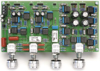
The finished board pictured in Figure 4 should be taken as an example to work from — success is guaranteed if you strive to achieve this level of perfection in construction.
Do not forget to fit JP1 for the ground through connection, a similar jumper is present on the MC/MDMM board. This allows you to determine empirically which ground connection works best. When the wiring is complete one jumper has to be fitted, or both.
Axial polystyrene caps require care in determining where to bend the legs. Their size is not standardized and subject to various tolerances compared to other parts.
Finally, on the potentiometers, plastic types from Vishay Spectrol may be used instead of cermet.
Discussion (39 comments)
600duke 2 years ago
Hello Collin,
After I had already asked how the ground-GND-minus is connected, I have not yet received a concrete answer. Again and again I try to connect the preamp so that everything works correctly, but unfortunately I can't get any further. I have to connect the ground minus with a capacitor on the input/output board so that a relay is controlled at all. The same happens with the two relays on the sound and volume circuit board, only when I connect the Ton-Defeat cable with plus and zero of the input connection 17+ 0 17- do the relays switch! That can't be the solution! Unfortunately, my preamp still doesn't work. The problem is probably the common ground connections of the individual boards. I just do not get any further! How is the mass realized? Why isn't the inputselect board connected to ground? If I remove the jumper from the tone control circuit board, a scratching noise is produced. I currently only have the Ton-Klang board connected to the front board and the in/out board.
Please help me to realize the project. All other connections were checked again and again.
A pictorial representation would help many people. Thanks Collin
600duke 2 years ago
Hallo Collin,
Nachdem ich schon mal gebeten hatte wie die Masse-GND-Minus verbunden wird, habe ich noch keinen konkrete Antwort bekommen. Immer wieder versuche ich den Vorverstärker so zu verbinden das alles korrekt funktioniert, doch leider komme ich nicht weiter. Ich muss die Masse-Minus mit einem Kondensator auf der ein-Ausgang-Platine verbinden so das überhaupt ein Relais angesteuert wird. Das gleiche passiert mit den beiden relais auf der Klang und Lautstärke Platine, erst wenn ich das Kabel Ton-Defeat mit Plus und Null des Eingangs Verbindung 17+ 0 17- verbinde, schalten die Relais! Dass kann die Lösung nicht sein! leider funktioniert mein Vorverstärker immer noch nicht. Das Problem sind wohl die gemeinsame Masse Verbindungen der einzelnen Platinen. Ich komme einfach nicht weiter! Wie wird die Masse realisiert? Warum ist die Inputselect-Platine nicht mit Masse verbunden? Ziehe ich den Jumper von der Klangregel-Platine ab, entsteht ein kratzendes Geräusch. Ich habe zur Zeit nur die Ton-Klang Platine mit der Front-Platine und der ein-Ausgangsplatine verbunden.
Bitte helfen sie mir bei der Realisierung des Projektes. Alle anderen Verbindungen wurden immer wieder überprüft.
Eine bildliche Darstellung würde vielen Menschen helfen. Danke Collin.
truonggiangpc 2 years ago
Alen alen s 3 years ago
Calpe 3 years ago
Joachim Hubertus Hendriks 3 years ago
leider funktioniert mein Vorverstärker immer noch nicht. Das Problem sind wohl die gemeinsame Masse Verbindungen der einzelnen Platinen. Ich komme einfach nicht weiter! Wie wird die Masse realisiert?
Bitte helfen sie mir bei der Realisierung des Projectes. Alle anderen Verbindungen wurden immer wieder überprüft.
Eine bildliche Darstellung würde vielen Menschen helfen. Danke Collin.
C Gunn 3 years ago
I Am assuming you build your preamp with all the component designed by Elektor .
The power supply board has three +17, 0, -17 volt outputs
1-- Main Preamp board with volume, Bass, Treble and balance
2--Phono board for the MC and MM cartridge turntable pickup
3 - The LLLL board ( I did not build this disco light )
These three board have a jumper connection to ground .
Use only ONE of these jumpers to ground .
This one ground connection is used through out the design.
From the input selection to the output jacks to your amplifier.
On the input selection also has jumpers to ground.
Your decision on the type of input RCA or XLR will define how you place these grounds
Do not to forget the jumper is in place on the JP block of your selected input
Start with a RCA jack on one selected input and try your preamp .
Do not to forget the jumper is in place on the JP block of your selected input
Have posted more information in Hanno Reimann board
Good luck ,
Hanno Reimann 3 years ago
1 Massepunkt für den gemeinsamen Anschluss wird von Dir definiert. Meistens ist das der Elko nach dem Gleichrichter bzw. der letzte Elko nach der Siebkette. Wenn ein externes Netzteil benutzt wird, sollte man auf jeden Fall noch ein RC- oder LC-Siebglied hinzufügen. Um weitere Störungen, die über die Stromversorgung der OpAmps eingespeist werden können, zu unterdrücken, speise ich die Stromversorgungspins niemals direkt von den Versorgungsspannungen, sondern gehe grundsätzlich über ein RC-Glied in die Stromversorgung der ICs. Bei Vorverstärkern meistens über 100 Ohm und 22uF ..100uF.
Leider musst Du das auf der bestehenden Platine aufwendig hinzufügen.
600duke 2 years ago
Joachim
Hallo Hanno,
Nachdem ich schon mal gebeten hatte wie die Masse-GND-Minus verbunden wird, habe ich noch keinen konkrete Antwort bekommen. Immer wieder versuche ich den Vorverstärker so zu verbinden das alles korrekt funktioniert, doch leider komme ich nicht weiter. Ich muss die Masse-Minus mit einem Kondensator auf der ein-Ausgang-Platine verbinden so das überhaupt ein Relais angesteuert wird. Das gleiche passiert mit den beiden Relais auf der Klang und Lautstärke Platine, erst wenn ich das Kabel Ton-Defeat mit Plus und Null des Eingangs Verbindung 17+ 0 17- verbinde, schalten die Relais! Dass kann die Lösung nicht sein! leider funktioniert mein Vorverstärker immer noch nicht. Das Problem sind wohl die gemeinsame Masse Verbindungen der einzelnen Platinen. Ich komme einfach nicht weiter! Wie wird die Masse realisiert? Warum ist die Inputselect-Platine nicht mit Masse verbunden? Ziehe ich den Jumper von der Klangregel-Platine ab, entsteht ein kratzendes Geräusch. Ich habe zur Zeit nur die Ton-Klang Platine mit der Front-Platine und der ein-Ausgangsplatine verbunden.
Bitte helfen sie mir bei der Realisierung des Projektes. Alle anderen Verbindungen wurden immer wieder überprüft.
Eine bildliche Darstellung würde vielen Menschen helfen. Danke Hanno!
PS. leider kann ich hier kein JPG hochladen...?
600duke 3 years ago
guter Vorschlag, Danke
C Gunn 3 years ago
I did not make any modification from the designed schematic .
Using Elektor 04/2012 schematic main preamp , Terminal K8 shows a JP1 jumper pin .
Using Elektor 05-2012 the Phono Schematic , Terminal K8 shows JP3 jumper pin .
Did not Build the LLLL board and therefore the connection to K17 is not made
Used ONLY ONE of these jumpers( JP1 or JP3) as the ground back to the power supply .
More than one ground jumper will create a circuit loop through the design
This may create a hum or unwanted noise.
This should NOT cause a failure in the system .
Power OFF
You should be able to check your grounding by removing the ground jumper from both JP1 and JP3
Use an Ohm meter on K3 or K4 Ground and on K8 0 ( preamp board)
The reading should be infinite or open
Do the same on Phono board K4 ground to K8 0 .
The reading should be infinite or open
Place one Jumper back in place and the reading at both spots should be 0 Or closed.
Did you build the complete project , Preamp , Phono amp, LLLL board and power supply?
Good Luck
C Gunn 3 years ago
I do not speak german but have translated your message using software translator
I must ask did you build the power supply which was part of the project
Elektor 06-2012
Using this Article for the Input power supply, Front Panel and Input Selection
IC3 is the power supply to control the input channels to the preamp . If this does not work properly you will get nothing in to the preamp
Check VRE K4 form the power supply is correct .
Check VRE K6 on the Front Panel ** note there was a correction notice from Elektor that the polarity were wrong on the PCB
D1 Front panel board should be ON
From your front panel select and change one of the 4 relay ( RE1A - RE2A, RE 3A and RE4A)
These relays are on the input selection . If this works Please let me know .
Power OFF
Place an Ohm meter on Input Selection K17 terminal 1, 3, 5 and 7
Place the other Ohm lead onto K6 Front Panel Negative or Ground side
Rotate S5A and check your Continuity at these points
The Input Selection Switch S5A selects ground or negative side of VRE from K6
The problem which I had was the switch The Lorlin CK1050 suggested in the component list .
This switch is selectable and you may not have set it up .
You should be able to turn On and Off RE1A- RE4A first.
power supply.pdf (557kb)
input selection.pdf (405kb)
Alen alen s 3 years ago
C Gunn 3 years ago
I used 4 wire flat ribbon to wire between connection boards , preamp and phono amplifier .
Do not ground every point listed on the diagram as you do not want to create ground loops
The rotary selector switch for the input selection should be setup before mounting. The switch only requires 4 position and in the correct sequence .
3071daniel 4 years ago
Demenslens 2 years ago
Henk Lensing
Marwei 5
Delfstrahuizen
demenslens@outlook.com
Bill Genefaas 3 years ago
Cheers,
Bill
3071daniel 3 years ago
Cheers
Henk Aartse Tuijn 3 years ago
I have all the PCB's for sale, most of them are for 75% stuffed.
Because I'm not home now I will fotograph the boards tomorrow and send them to you OK.
Greetings,
Henk
Henk Aartse Tuijn 3 years ago
Underneath the promissed fotograph's
Awaiting your comments,
Best regards,
Henk
img-20210502-122518.jpg (572kb)
img-20210502-122954.jpg (819kb)
img-20210502-123506.jpg (1179kb)
img-20210502-123557.jpg (866kb)
3071daniel 3 years ago
hicoco 3 years ago
600duke 4 years ago
Hello, unfortunately it's always the same with Elektor projects, everything is presented for a good sale of the individual project parts. What bothers me, however, is that you are left alone with many projects!
Here, too, it was promised that a complete connection of the components would be shown in the network.
Nothing like that happened. Unfortunately no answer to inquiries.
My question about this, how are the individual boards connected to each other with the MASS ???
So that they finally work ...
Calpe 4 years ago
C Gunn 4 years ago
Stacked the preamp board on top of the Phono board . Stacked the two I/O boards on top of each other
Did not mount the Channel select and the LLLL switch to the PCB . Mounted them to the front board then wired them to the PCB .
Mounted the transformer to the bottom then stacked the Power supply on top
Electronpair 3 years ago
I hope it is OK to directly contact you here in the comments section. You have said, that you posted file which shows the completion of preamp. Where can I find this file?
Kind Regards
Phil
PS: Which connectors did you crimp with the Iwiss SN-28B?
C Gunn 3 years ago
Open my comment on Treble control .
There is an attached photo of my Preamp as it sits in my designed cabinet .
I used SolidWorks and had the wood cut on a cnc machine
Not sure if I can post Solidwork files onto the forum
If you want more Photos le me know
ElektorLabs 4 years ago
Joachim Hubertus Hendriks 4 years ago
It is certainly clear to me and colleagues in the forum that this preamplifier was 10 years ago
Came out. However, not everyone always had time to complete or finish one project after the other. However, the price also plays a role.
It is clear to everyone that they have one of the best preamps on the market!
Specifically, it is about the sentence from elektor 06-2012 page 55. It is important that the masses of
Audio part and relay are only connected at a single point in the power supply unit.
The relays are not switched with me ... where should I actually connect the ground?
On the front board, input stage, and phono and preamp?
If you could tell me that, I would be looking for errors after months of unsuccessful troubleshooting
put the preamplifier into operation.
I and others look forward to a constructive answer, thank you and greetings Joachim
ElektorLabs 4 years ago
Proceed methodically to isolate the problem:
0. Get a lab (or other known functioning reliable) power supply with 12V output, 500 mA should be enough.
1. Check the relay types mounted on the boards (12V, DPDT, is the pinout correct? Check this!).
2. Check the soldering. Contacts are good?
3. For each relay, apply 12V directly to its coil (touch it with two wires) and listen for the "click" sound.
4. Apply 12V to the relay connector (e.g. K5 on the main board 110650-1). Do the relays click?
5. Connect the switch board 110650-4 to the circuit board under test (e.g. the main board 110650-1)
6. Apply 12V to K6 of switch board 110650-4
7. Use a screwdriver or jumper to emulate switches S1, S2, S3 (or use real switches, but test them first, do they switch?). Do the relays click? With a wire connected to ground touch the rotary switch contacts. Do the relays click? Now try with a real rotary switch. Do the relays click?
If you get this far you know that the relays are working and the relay wiring is working too.
8. Replace the lab supply by the project's power supply 110650-5 and try step 7 again.
Note that in all these tests the power supply is never connected to the audio circuitry.
At this point you can add the audio circuit to the test. Short all inputs. Do you hear relay noise in the audio output signal? Try with and without the ground jumpers (JP1 on 110650-1, JP3 on 110650-2). If there is no noise, then there is no problem. Otherwise see if things improve with a wire between K4 0V pin and K2 0V pin (both on PSU board 110650-5) or between K4 0V pin and K5/K6 common pin.
Hope this helps.
C Gunn 4 years ago
The Lorlin type CK1050 is an adjustable switch.
Its setting are made by the placement of the lock ring behind the lock nut .
This setting can be found in Lorlin data sheet.
Start by checking that there is continuity to ground on K1 1-7 as you rotate the switch .
This setting is required that you get the 4 selection in row
C Gunn 4 years ago
The polarity of K6 was incorrectly labeled on the PCB on some of the original PCB
If the polarity is correct and the power supply has been applied to K6 the D1 LED should be on
This also means there is a good ground from the Front Panel board to the relays
600duke 4 years ago
Joachim Hubertus Hendriks 4 years ago
600duke 4 years ago
Auch hier wurde versprochen das ein gesamt Anschluss der Komponenten im Verbund dargestellt wird.
Nichts ist dergleichen passiert. Bei Anfragen leider keine Antwort.
Meine Frage hierzu, wie werden die einzelnen Platinen miteinander mit der MASSE verbunden???
Damit sie auch endlich mal funktionieren...
Danke
Alan Peterson 4 years ago
3071daniel 3 years ago
ElektorLabs 4 years ago
Henning Hansen 4 years ago
My adress is : henning@hnhau2mat.dk
jorgevitorino1@hotmail.com 4 years ago
Sorry the question I need help too know the better power supply for this preamplifier?
(P.S: Sorry my English)
C Gunn 4 years ago
The power supply in the article works fine with the preamp .
Why do you need a different power supply?
C Gunn 5 years ago
The sound overall is impressive but have one concern and that is the treble adjustment
There is none
Have connect a AC volt meter to the output to monitor amplitude change while making adjustment to the treble . Have not seen any change on either channel
Any comments or suggestion would be Appreciated
The bass amplitude voltage change is huge.
Alen alen s 3 years ago
C Gunn 5 years ago
Used function generator , oscilloscope and multimeter.
The level of changes were as you stated .
Need to get my ears checked or listen to music with a higher frequency response.
ElektorLabs 5 years ago
Use a function generator or test CD to measure levels when changing bass and treble. There is lot of freeware that can use onboard audio or sound card of a PC for audio measurements, turn it into a generator and oscilloscope. Use 40 Hz and 20 kHz. If you use a multimeter check the level of 40 Hz, 1 kHz and 20 kHz at the output from your source (CD or DVD player, PC) to see whether they are the same, so to make sure the bandwidth of the multimeter is sufficient. Maximum change at these frequencies should be +/- 10 dB. This is approximately a change from 3 times (3.16) greater to 1/3 (0.316) of the level in mid position of the potentiometers. Look at the bass/treble graph for reference. At 1 kHz there should be almost no change in amplitude.
Measuring capacitors in-circuit is difficult to interpret. Have a look at the capacitors. On them the number for the value is much like color code for resistors, so in this case ‘104’ means 10 * 10^4 * 1 pF = 100 nF.
C Gunn 5 years ago
There is a notable sound difference.
C Gunn 5 years ago
If the bass was set to minimum and the treble set to minimum .
Volume steady
Then increase the treble to maximum .
I used the Elektor LCR meter for the following test and measurement
Power off. Removed IC4 from socket
Placed the leads from the LCR meter into the IC4 socket pin 1 and 2
Meter High side is on 2 and low side is on 1
Treble pot turn fully counter clockwise
LCR meter @ 10khz
Meter reading 1.0269k ohms , 2.531 nF ,Q 0.163 , Vvx 354.5mV, Ix 349.7 uA
Treble pot turned fully clockwise
Meter reading 1.8697K ohms , 709.6 pF , Q 0.083 , Vx 369.3 mV, Ix 198.2 uA
With treble pot connected in parallel with R17 as the treble pot is increased should I not see the over all Ohmic value go down
ElektorLabs 5 years ago
Beautifully build! Looks good.
Calpe 6 years ago
In the BOM list BOM-110650-4_front-v1.2, they are listed as: -
SWITCH, SPDT (On-On), Multicomp, 1MS1T1B5M1QE, S1-S3, Farnell code 9473378.
But in Farnell's web site this switch is given as a 'Toggle Switch, SPDT, On-None-On.
On checking it's switching, when the actuator is moved the centre leg switches to either one or the other contact legs and does not have a centre OFF position.
Is this switch ON-ON or what type is it or should it be?
Any ideas from where i can obtain 3 black toggle switches?
TonGiesberts 6 years ago
Pascal Hibon 6 years ago
1) Can anyone explain to what the function of J3 is on the MM / MC preamp PCB? This jumper connects the power supply GND to the phono preamp's GND. I would imagine this jumper should always be closed. What is the pupose of that jimper?
2) The 2SA1085 transistors are no longer available. Which replacement do you advice?
Would KSA992 be a valid replacement?
3) Question about the gain. According to the article, the MC section has 45dB of gain. So, if I need a total of 60 dB for a particular MC cart, I need to set the JP1 and JP2 jumper for 15 dB (45 + 15 = 60). Is that a correct assumption?
Thank you!
Pascal Hibon 6 years ago
When I turn up the volume quite a bit there is some noise and a bit of hum noticeable. The preamp's gain is currently 60 dB in MC mode; I guess there is a price to pay with such gain setiings. But I'm wondering if this could be improved by using the original 2SA1085 transistors (I'm using KSA992 transistors right now).
Has anyone else finished the preamp and tested the phone preamp? I would love to hear you comments.
I have attached some pictures of my work in progress.
The guts (159kb)
Pascal Hibon 6 years ago
The answer is written in part one of the project. Page 17 of the article in magazine 04-2012 has a block diagram that explains it correctly.
For my case I need 60 dB of amplification for my AT-OC9/III cart. I need to set jumper J1 and J2 for 0dB. This will result in a total gain of 60 dB:
* The MC input section has 30 dB of gain.
* The total gain of the MM setion is variable from 30 dB (jumers J1 and J2 at 0dB) to 50 dB (jumpers J1 and J2 at 20 dB).
So for my case I need 30 dB (MC section) + 30 dB (MM gain jumpers at 0dB) = 60 dB. This part was not cleary explained in part 2 of the project and caused confusion to me.
Pascal Hibon 6 years ago
Thanks for the J3 explanation. That makes sense and I haven't thought about that since I'm using the phono preamp standalone.
Still waiting for my gain question to be answered though. Hope someone from Elektor will chime in.
C Gunn 6 years ago
J3 can be the ground point for the module . Follow through the circuit and you will see other points where a ground can be established Eg input section The Phono K5 & K7 can be grounded through S4 .
Have recently purched SA 1085 transistors on Ebay . they are still avaialbe
Ordered 10 For $30 which included shipping.
The gain has multiple option and that is your choice on your taste for music and the level at which you wish to hear it . Enjoy.
Calpe 6 years ago
As for the T1 - T8 = 2SA1085, the suggested replacement shown in Farnell is a KSA992FBU, order code 2453942, it's what ive used.
Gain (as written in PT2) - 'The gain is varied in 5 db steps by a jumper on jumper block JP1 selecting the desired tap on the negative-feedback divider R36-45'.
i.e. JP1 - 1 & 2 = 0 db; 3 & 4 = +5 db; 5 & 6 = +10 db; 7 & 8 = +15 db; 9 & 10 = +20 db.
Also be aware of the optional value variations for the following: -
Left Channel - C8, R13, C1, R1
Right Channel - C35, R61, C28, R49
I'm still of the opinion that this project needs an urgent rewrite, showing all corrections etc to be published for all concerned. Although a project from 2012, it's still being built!!!!
A complete circuit diagram should also be available to be downloaded/printed.
One day i might have my very expensive build, up and running!!!
Calpe 7 years ago
1 x 110650-1 v1.2
1 x 110650-2 v1.2
2 x 110650-3 v1.3
1 x 110650-4 v1.1 (we know that K6 is wrongly labelled)
1 x 110650-5 v1.1
1 x 110650-6 v1.2
Having the above pcb versions has their been any circuit changes or modifications of any kind effecting these pcb versions?
Or indeed any other circuit changes that i should be aware of?
Calpe 7 years ago
I'll post my checks here tomorrow.
Thanks
C Gunn 7 years ago
TonGiesberts 7 years ago
Calpe 7 years ago
Could someone please explain in detail about this?
Elektor 06-2012, page 25
"the audio ground and the relay ground must be connected together at one point only, right back at the power supply; othwerwise relay currents flowing in the audio groundwill cause unpleasant clicking noises in the preamp output".
TonGiesberts 7 years ago
Calpe 7 years ago
The supply voltages are all ok, +17, 0 and -17v.
D1 led also lights when powered on.
D2 led i have not seen lit, despite numerous combinations of S4/S5 etc.
My question is to try and clear up the position and mounting of S4 and S5.
Both these rotary switches can be mounted any way on the Front panel pcb.
Can someone please advise how exactly they should be mounted?
Lastly, to enquire about K6 socket and the +Vre/0 connections.
Following +Vre from the PSU to K6, you'll see that the +Vre on K6 does not go to R1.
top side (591kb)
Calpe 6 years ago
A query to the Elektor team and maybe some other builders might know.
What is the known operating temperature of this Preamp?
Obviously it doesn't run cold, just a bit concerned by the warmth given off after it's been on for some time.
Pascal Hibon 6 years ago
I would leave the power supply at +/- 17 volts because that will give you more headroom (and probably a bit better SNR numbers).
The datasheet can be downloaded from this link:
http://www.ti.com/lit/ds/symlink/ne5532.pdf
Calpe 6 years ago
Therefore lowering R2 & R4 from 1K3 to 1K1 will give a PSU output of +/- 15V.
Therefore the +Vre supply won't be effected, supplying on K4's output the 0v and +15V.
If +15V is supplied from K4, then on R1 Front Panel you would have +15V.
So it's assumed that the +10.43V on the other side of R1 is enough to power the 12V Relays on the two Input Boards?
Lastly, will the heat given off from the PSU heatsink, cause the electrolytic capacitors to dry up quicker than normal?
Calpe 6 years ago
Shows in stock....
hicoco 6 years ago
I would like to start next month this DIY, after having read this forum i fund that the PCB are no longer available in the online store, would it be possible to purchase the GERBER files updated so I can have a set of PCB made ?
Thank you !
Calpe 7 years ago
The Front Panel pcb i have is v1.1, and it appeared strange that on the top side of the pcb it shows +Vre to be the left connection and 0 to be the right one. Therefore following +Vre through to the print it does not go to R1 and shown on the circuit diagram. See attached image.
My query was based on actual fitting S4/5 on the Front Panel pcb, as it appears they can be fitted turned around and still fit into the pcb holes.
Jumpers on JP1-4 are fitted and i'm using left and right RCA's just for initial testing.
Jumpers on S1-4 i have chosen not to fit.
I have now removed all the wiring with just the two Input pcb's connected with the Front Panel.
I'll begin checking the audio (RCA) input tomorrow and trace with an old scope to see what's happening.
Thanks
TonGiesberts 7 years ago
Test the line / tone / volume / output board, moving coil / moving magnet preamplifier board and the 2 input boards individually. Check if the relays on all boards work. Don’t forget to place jumpers on S1…S4 on the input, selecting balanced or unbalanced input configuration of K1/K3/K5/K7. If instead the RCA phono connectors K2/K4/K6/K8 are to be used check if jumpers are in place on JP1…JP4.
Placement of the front panel board and thus the exact position of the rotary and other switches is left to your own assessment. It’s very subjective what the front panel should look like and the reason we leave this to your own preference. This choice was also made because it largely depends on type and size of the enclosure used. The connections to the switches are very basic and you might consider not using the front panel board and connect the switches (choose ones with solder lugs) and LEDs by direct wiring from their position on the front panel to the different boards. Just an idea. No critical signals are used here.
C Gunn 7 years ago
D2 works in conjunction with the LLLL board and with not light unless it is turned on and has an input.
The rotary switches are divided into two (switch a and b) the pins in the back of the switch is the seperation position. As long as the pins were installed you should ok.
The +VRE is supplied to each relay on the input boards . through K1 (2,4,6,8,10)
switch S5A position which relay on the input board is switched to the 0 of the PSU
Would not worry about switch 4 right for now .
Check your voltage on relays RE1a, Re2A ,Re3a and RE4a (2,4,6,8,10) should have +VRE at all times. Only one relay is turned on when S5A is switch to GND or 0 of th PSU.
R1 is connected to K6 check for a cold solder.
Calpe 7 years ago
'Axial polystyrene caps require care in determining where to bend the legs. Their size is not standardized and subject to various tolerances compared to other parts.'
Can someone kindly enlighten me about this, as no other explanation is given?
TonGiesberts 7 years ago
Calpe 7 years ago
Can someone clear up what is written of the fuse F1 (230VAC) = fuse, 0.315A Antisurge?
What is the correct mains input fuse that should be used on the mains input circuit?
Hanno Reimann 7 years ago
Hanno Reimann 7 years ago
Calpe 7 years ago
Was there any mention of it by Elektor?
Elko behind resistor?
I'll be beginning to wire all the boards from tomorrow.
Calpe 7 years ago
Can anyone please give me any advise and steps that i should take and be aware of when doing the wiring?
Are there straight forward guides available of all the connections, including the d.c. connections?
With thanks
Calpe
Calpe 7 years ago
1500FH 7 years ago
I find it a very good idea to add a Bluetooth module, but be careful. The implementation of this type of component is not as simple to achieve as it automatically implies the SMD (which is not the case of the rest of the circuit). And then there is the whole programming part.
If we go to the digital channel, it's a shame to stop only Bluetooth. As well provide a complete card AD-DA with Bluetooth, USB, Coax, RJ45, ...
But in this case, it's another much more ambitious project.
But is it reasonable to have only an analog preamp in 2018?
Calpe 7 years ago
ClemensValens 7 years ago
Calpe 7 years ago
Calpe 8 years ago
Calpe 7 years ago
Ive only got PCB's -5, -4, -2, -1 and -6.....
PREAMPLIFIER 2012 INPUT BOARD (110650-3)
Sorry
C Gunn 7 years ago
Would like to know if you have PCB 110650-3
Initial planned to only build the Preamp and then decided to build the Phono amp .
I only purchased one PCB board and need another . They are now sold as a complete set.
Calpe 8 years ago
Can i first suggest that it is very important to read all the comments in the Preamplfier 2012 forum.
An important point is that the i.c.'s needed (it's now 2017) have a lower working voltage, so there is a small change of a couple of resistors in the Power Supply, to lower the voltage supply.
This web site is extremely helpful too, many people offer suggestions and help: -
http://www.diyaudio.com/forums/chip-amps/214635-ne-5532-preamplifier-doug-self-elektor-2012-a-4.html.
I also post in the DIYAUDIO web site, so ill see you there.
Many people have built the Preamplifier and you'll see my posts there too.
Regards
3071daniel 8 years ago
I discover this forum and I am thinking to start this project.I already received all the PCB.The questions is should I order all the parts and start the project ?.
You already made a big job .
How can I contact you ?.
TBH
Calpe 8 years ago
Please request here
Calpe 8 years ago
The Input pcb has a connector K17, a 10-way boxheader.
In my case having a Left and Right channel then both K17 connector need to be joined.
This cable in turn then needs to be connected to K1 on the Front Panel pcb.
Can someone please advise me what cable (Farnell code no.?) needs to be used?
Calpe 7 years ago
Calpe 8 years ago
In the final stages of having mounted all components and sockets i now need to look for a way to mount the PCB's allowing of course for the Controls, switches and input/output sockets, Mains socket.
As we know the PCB's needed to be mounted are: -
1. Line / tone / volume / output PCB
2. Input PCB
3. Front Panel PCB
Clearly a template must exist to be able to mark out the hole to be drilled etc.
Help would be appreciated on how to interconnect the pcb's and what type of cabling/connections should be used.
Has any type of case ever been recommended?
Calpe 7 years ago
But i'm stuck! No Templates!
As I have all the components mounted on the pcb's, assembly needs to be done and mounted in a case.
The case used is the R.S. PF-19 Ventilated Rackmount Enclosure with Handles, 2U, 84 HP, 245mm Deep, Stock No. 665-7719.
As there is disappointingly no template/s in the project, how is it expected to drill the holes for the preamplifier’s input board, having so many sockets etc.?
I have read in DIY Audio web site that some constructors have used a PC program Front Panel Designer, but i wouldn't have an idea how to use it....
Can someone please help?
This project is not a cheap one to build, and the least you would expect from the Elektor team would be the template.
Calpe 7 years ago
Calpe 7 years ago
Clemens, ive been looking at the PCB design, and i can't see how it's possible to be able to get templates for the PREAMPLIFIER 2012 INPUT BOARD and also the PREAMPLIFIER 2012 FRONT PANEL BOARD, if all the components are in place and soldered.
What is actually needed is a template to be able to drill the holes for all the Inputs on the Input Board and also for the switches that are mounted on the Front Panel Board.
Any ideas please.
ClemensValens 7 years ago
Calpe 7 years ago
Anxious to build it, i have mounted everything, so it's too late to use the pcb designs as a template.
I would have thought in such a popular project Elektor would have thought about these things.
Disappointed
ClemensValens 7 years ago
Calpe 7 years ago
Surely, Elektor should give better support than this?
Calpe 8 years ago
Let's hope they respond
Alain Simard 8 years ago
Calpe 8 years ago
Calpe 8 years ago
Under this number it is actually a Non-Polarised capacitor 10uF 63V.
On page 26 of Preamplifier 2012 (3) C12 is actually a 10uF 63V, and should not be Non-Polarised
Martin Nilsson 8 years ago
Calpe 8 years ago
C12 = 10μF 20% 63V, 6.3mm diam., 2.5mm pitch
Using Farnell UK web site you find several, take your choice on price etc.
On their web site you can filter based on the above spec. but one of these would do the job: -
Order no. 1165532, 1870986, 1871027
Martin Nilsson 8 years ago
Have you been able to licate the accurate farnell number?
Calpe 8 years ago
Under this order no. 1236687 is actually a Non-Polarised Electrolytic Capacitor, 2.2 µF, 100 V, MCNP Series, ± 20%, Radial Leaded, 6.3 mm.
On page 22 of Preamplifier 2012 (3) C1-C4 are listed as 2.2uF, 100V, and should not be Non-Polarised.
Calpe 8 years ago
"Component positions R1 and C1 are provided so the cartridge loading can be modified. This has only a marginal effect on MC cartridge response in most cases because the cartridge impedance is so low. However, if you want to experiment then the appropriate range for R1 is 10Ω- 1kΩ, and for C1 is 0 – 10nF.
Component positions R13 and C8 are provided so it can be modified. The appropriate range for C8 is 0–330pF."
Rather than experiment (avoid damage to pcb) might there be 'normal' values that could be used?
Calpe 8 years ago
TonGiesberts 8 years ago
Calpe 8 years ago
Boards originally purchased from Elektor.
Boards are: -
PREAMPLIFIER 2012 (110650-1) (LINE-IN/TONE/VOLUME BOARD)
PREAMPLIFIER 2012 (2) (110650-2)
PREAMPLIFIER 2012 INPUT BOARD (110650-3)
PREAMPLIFIER 2012 FRONT PANEL BOARD (110650-4V110)
PREAMPLIFIER 2012 POWER SUPPLY BOARD (110650-5V110)
PREAMPLIFIER 2012 LLLL BOARD (110650-6V120)
Calpe 8 years ago
http://www.diyaudio.com/forums/swap-meet/302020-elektor-preamplifier-2012-pcbs.html
Calpe 8 years ago
Due to the latest interest in this project that was released in 2012, new requests for the PCB's, opinions and views etc, many things have been changed over these four years that affect the building of this project.
May i suggest due to the vast popularity of this project, that an up to date Preamplifer 2012 be issued that lists all the changes: -
The i.c.'s that were listed back in 2012, now in 2016 the versions available operate on a lower voltage and thus the voltage supplied has to be lowered.
Detailed information on the wiring, and type of wire to use.
Plus all and any other items
Telefunken 8 years ago
Thank you !
Telefunken 8 years ago
That will be fun to build and listen to !
Best regards, Claude
Calpe 8 years ago
https://www.elektor.com/preamplifier-2012-1-line-in-tone-volume-board
PREAMPLIFIER 2012 (110650-1) (LINE-IN/TONE/VOLUME BOARD) £23.00
https://www.elektor.com/preamplifier-2012-2
PREAMPLIFIER 2012 LLLL BOARD (110650-6V120) £14.95
https://www.elektor.com/preamplifier-2012-front-panel-board
PREAMPLIFIER 2012 FRONT PANEL BOARD (110650-4V110) £12.00
PREAMPLIFIER 2012 (2) (110650-2) £23.00
PREAMPLIFIER 2012 INPUT BOARD (110650-3) £22.95
PREAMPLIFIER 2012 POWER SUPPLY BOARD (110650-5V110) £16.95
ClemensValens 8 years ago
Telefunken 8 years ago
By chance would you have the gerber files for the other boards needed to build this project as well ?
They are number : 110650-2, 110650-3, 110650-4, 110650-5, 110650-6
By the way I wrote to the person in charge of the store and she said that these PCB's will not be restocked.
So that's why I'm asking for help.
Thank you again for your help and best regards.
Calpe 8 years ago
Calpe 8 years ago
As you have seen 'You can leave your email-address here so we can notify you as soon this product is deliverable again'.
I have purchase the pcb's and the quality looks superb!
Calpe 8 years ago
Of course allowing for their input/output impedances and signal level input/output?
Thanks
Calpe 8 years ago
Although it's 'normal' practise to have the volume at minimum before any connection or switch-on, it is a little concerning that 'if' ever the input reached 400mV then the output +ve would reach 2.6v.
TonGiesberts, could you kindly advise what type of cable should be used to connect the all pcb's together?
I haven't seen any Farnell code no. in the project article and i must order the correct type of cable from Farnell when i place my order (in the basket at the moment) for the components.
Thanks
TonGiesberts 8 years ago
Calpe 8 years ago
Clearly, i don't want a mis-match with impedance or signal i/p & o/p's being wrong.
Accordingly, from what i've understood, the Preamp kicks out 1.3v max.
As can be seen the Q-Watt only needs 0.88v i/p = 137W o/p.
Although the o/p is controlled by the volume level, what could happen if the volume shot up to 1.3v? A blown Q-Watt amp having been pushed to its limit?
This to me is concerning.
As the components for the Preamplifer run up to several hundred pounds, i'm now in doubt whether to continue or not despite the costs of the pcb's.
Calpe 8 years ago
Preamplifier spec states: -
THD+N (200 mV in, 1 V out)
0.0015% (1 kHz, B = 22 Hz – 22 kHz) Max. output voltage
0.0028% (20 kHz, B = 22 Hz – 80 kHz) (200 mV in) 1.3 V
Output impedance = Not stated in Elektor article !
Q-Watt spec states: -
Input sensitivity: 0.88 V (137 W / 8 Ω, THD+N = 0.1%)
0.91 V (145 W / 8 Ω, THD+N = 1%)
Input impedance: 15 kΩ
Calpe 8 years ago
Calpe 8 years ago
I still can't order the components needed as i need to include the cable needed.
There doesn't appear to be any reference in the article to what cables were used.
There must be a Farnell / RS code number.
Can you please advise.
Calpe 8 years ago
Thinking about it, its probably better to post things here in its original location - Elektor Preamplifier 2012.
Martin Nilsson 8 years ago
Calpe 8 years ago
Martin Nilsson 8 years ago
Do you frequent the diyaudio.com forum?
I had i mind to share my project on a thread there and perhaps you would like to share it?
Would be a good place to exchange ideas as well?
Martin Nilsson 8 years ago
That is brilliant work! Extremely useful.
Really looking forward to hear about your project as it progress.
Calpe 8 years ago
Martin Nilsson 8 years ago
I just signed up for a membership with the intention of building this preamp.
I have read through the entire discussion on this article and I was hoping to take advantage of your experience working on this project and the parts required.
How is your project progressing?
Kind regards
Calpe 8 years ago
For audio cable check here: -
https://www.thomann.de/gb/cordial_cik_122_sw.htm
To avoid numerous courier charges, especially Thomann's, i looked in Farnell comparing the spec. and came across this: -
1891100 - VAN DAMME 268011C Multicore Screened Cable, Audio Instrument, Per M, Black, 1 Core, 24 AWG, 0.22 mm²
Elektor have told me too connect the power supply voltages in the preamplifier use at least 0.75 square mm cable (19AWG):
Plus, Red, Pro Power, PP001270 (Farnell 2528175)
0/ground, Black, Pro Power, PP001186 (Farnell 2528082)
Minus, Light Blue, Pro Power, PP001249 (Farnell 2528151)
My Farnell order is now complete to send, many thanks to all the Elektor staff.
Calpe 8 years ago
I have patiently waited 3 weeks to be advised as I’ll need to include it with my pending Farnell order.
Much appreciated
ramdas narayanan 8 years ago
Calpe 8 years ago
ramdas narayanan 8 years ago
Actually I need the assebled board, if u dont have , atleast I need one PCB of the same,
So Can u please sent me the details for payment and all.
Need one PCB and Parts list
Regards
Ramdas
Calpe 8 years ago
Calpe 8 years ago
Calpe 8 years ago
FAIRCHILD SEMICONDUCTOR Bipolar (BJT) Single Transistor, PNP, -120 V, 100 MHz, 500 mW, -50 mA, 430 hFE
Calpe 8 years ago
K1, K3, K5, K7 = XLR socket, pcb mount, horizontal, 3-way
K11 = XLR plug, PCB mount, horizontal, 3-way
Having looked in Farnell, i'm not too sure which types to order?
Would you please advise which type of socket and plugs should be used?
I'd imagine that the Neutrik series AA sockets (1310019) would be the ones to use?
XLR Audio Connector, 3 Contacts, Socket, PCB Mount, Gold Plated Contacts, Plastic Body, AA Series
As for the XLR plug, PCB mount then i'd assume that (1310044) would be suitable to order?
XLR Audio Connector, 3 Contacts, Plug, PCB Mount, Gold Plated Contacts, Plastic Body, AA Series
Thanks
Antony Masefield 8 years ago
I guess the design folows the principles in Doug Selfs "Small Signal Audio Design" book which I have. Problem as always are PCBs hence my interest in this design.
I'll download the April to June mags and have a look.
If the power supply is the standard LM317/337 design type I have a couple of PCB's already with adjutsable output voltages.
Thanks once again,
Tony
Calpe 8 years ago
Calpe 8 years ago
This project appeared in April (part 1), Introduction and line-in/tone/volume board.
May (part 2) Moving-Coil/Moving-Magnet (MC/MM) board.
June (part 3) Level indicator, source selector, power supply.
All issues appeared in 2012. These can can purchase and download via https://www.elektor.com/magazines/single-issues-digital/year/2012/
The specifications for the Preamp are excellent!
As i was advised by Elektor 'In the earlier versions of this i.c. (and one other) they had a supply voltage of 18v. The '2016' version NE5532AP, only has a supply of +/- 15v and therefore to play it safe, it would be advisable to reduce R2 & R4 in the psu, from 1K3 to 1K1. The lower voltage shouldn't be a problem for standard signals'.
Antony Masefield 8 years ago
Could someone comment on which ones are required for a 'full system', what the purpose of each is, if they come with circuit diagrams and component lists or whether one needs to purchase the original articles for this information? If the later, was it just the April 2012 issue or was this project covered over a number of issues?
Sorry for the '20 questions' but I'm interested in building this one.
Thanks!
Regards,
Tony
ClemensValens 8 years ago
Calpe 8 years ago
Calpe 8 years ago
It would be ideal for all the constructors to be able to view a finished product.
Calpe 8 years ago
Any chance of 'seeing' the Elektor Lab's final product, fully wired etc?
ClemensValens 8 years ago
On GitHub you can find the Elektor Labs Preferred Parts (ELPP) list that contains Farnell & RS references for many parts that we use.
Calpe 8 years ago
Calpe 8 years ago
PCB's should arrive soon so I have to get down to checking who supplies what and go through the complete spares needed.
ClemensValens 8 years ago
Pin header: like Farnell 1098454
Pin socket: like Farnell 9728856
Box header: like Farnell 1654504
Double row pin header: like Farnell 1098460
You need plenty of jumpers, for instance Farnell 1740371
Box Headers mate with things like ribbon cable sockets, f.i. Farnell 1788710, that get pressed on a flat cable.
All these products can be had in different qualities/prices, pitches, and number of contacts. Look at the alternatives and accessories proposed by Farnell to see what more is possible.
Calpe 8 years ago
Calpe 8 years ago
ClemensValens 8 years ago
Calpe 8 years ago
ClemensValens 8 years ago
Similar story for the LM339, any type will do.
Calpe 8 years ago
Farnell show 4 versions TL072IP, TL072BCP, TL072ACP and a TL072CP.
These versions have slight differences.
Also can you advise with regards the LM339?
Farnell list LM339AN - N and NG.
Just to want to make sure correct type is ordered.
Calpe 8 years ago
Calpe 8 years ago
Code No. : 1608360, TE CONNECTIVITY / AXICOM V23105A5003A201 Signal Relay, D2n/V23105 Series, DPDT, 12 VDC, 3 A, Through Hole, Non Latching.
However, they show an alternative is the Code No. : 4219557 - Signal Relay, D2n/V23105 Series, DPDT, 12 VDC, 3 A, Through Hole, Non Latching, these are available.
Calpe 8 years ago
In addition i was kindly advised by customer services - that in the earlier versions of this i.c. they had a supply voltage of 18v. The '2016' version NE5532AP, only has a supply of +/- 15v and therefore to play it safe, it would be advisable to reduce R2 & R4 in the psu, from 1K3 to 1K1. The lower voltage shouldn't be a problem for standard signals.
ClemensValens 8 years ago