Ready to use for Breadboard. Small modules without wires [130276]

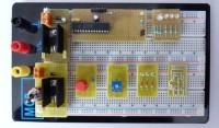
Ready to use for Breadboard. Small modules without wires : voltage regulator, 3 LEDs, pushbutton, potentiometer ...Voltage Regulator: small module that brings the power TO220 to the breadboard without wires but with a switch and an LED indicator. Mini-platinum: the same PCB for 3 leds or potentiometer or pushbuttun ... ready to use
Ready to use for Breadboard. Small modules without wires : voltage regulator, 3 LEDs, pushbutton, potentiometer ...
Voltage Regulator: small module that brings the power TO220 to the breadboard without wires but with a switch and an LED indicator. Mini-platinum: the same PCB for 3 leds or potentiometer or pushbuttun ... ready to use
I do other modules ready for use (see additional photos): PIC16F690, LCD, PIC24FJ64GA502 ....
Look at the photo noted voltmeter, only 9 WIRES !! : A 5V power supply, PIC16F690, LCD display 2 * 16, a potentiometer, an LED
Thanks you Marion


Discussion (4 comments)
NuttyProf 11 years ago
The only spacing that is constant between the various bread boards is the 2 sets of 5 pins with the space between them. This is because of standardised DIL chips. The modules PCBs should have a row of holes at 2,54 mm intervals so that they can have the pins for the supply put in according to the ones that match the bread board (BB) being used.
As to the modules, I think having an LED and resistor on a PCB or a preset resistor etc is a waste of time as this could be done on the BB its self. I think that useful modules to look at would be things like a 4017 with LEDs connected. The control pins of the 4017 (clock, inv clock, reset etc) are left open for the user to play with as pins on the BB. Also LM3914 and a ICL7136 with LCD and a 7224 counter with LCD and 4029 with LEDs, PIC module with LEDs, RS232 module and various other comon useful modules.
The secret to these modules is to also have them semi adjustable by using IC tulip pins for strategic components. Lets say a user has a project needing a 2 volt LM3914, so a simple case of setting 2 resistors in tulip pins on his module presets the input voltage for this. But also by clever layout these modules could be preconfigured with things like a floating negative reference so that a module could have an input of 10 to 15 volts on the LED display. This way the modules could have a preset configuration built in. In other words the modules are designed with all the possible configurations likely up front as well as have the control pins for the end user to play with.
The pins going to the BB could be the bottom end of long tulip pins. In this way later the BB could be removed and simply connecting wires from module to module via the tulip pins.
Finally all these modules should have a means to mount them into a box. Remember once the circuit is working it may have to go into a box and be used as such. Maybe look at some sort of standard configuration on this if possible? I generally use a 2,5mm hole in each corner and simply screw from the front straight into the PCB with a 3mm woodscrew. if the PCB is well thought out then the height of certian components will space the PCB off the front panel correctly. In the case of the LM3914 the LEDs are down below the height of the chip so the chip will be the spacer to the front panel. Quick and easy.
Lucky 11 years ago
I found two (unbranded!) breadboards here in the Elektor lab, apparently the distance between the outer (power) strips is not standardised. It looks like the smaller board's dimensions are most common, but it's really hard to tell and (almost) none of the suppliers specifies this distance in their catalogue or product spec sheets.
The larger boards measures about 5.4 mm between the two outer rows, the smaller approx. 4.7mm.
Let's vote ;-)
Lucky 11 years ago
arwin 11 years ago
PCA 11 years ago
Interesting idea.
I’m considering using this system for lab works with my students (https://www.facebook.com/ISILELECTRO).
Philippe
seen 11 years ago
Aubinais 11 years ago
ClemensValens 11 years ago
This is nice, especially the power supply board. The problem is to do it in a cheap way. I bought a cheapo sensor kit from Deal eXtreme with some 40 little PCBs like yours. When you look closely you notice that they have only a few different PCBs that they use for many different sensors. You too should limit the number of different PCBs as much as possible. How many different PCBs do you have now?
Regards,
Clemens
Aubinais 11 years ago