Review: Mini Scope
August 03, 2017
on
on
A few weeks ago, I was looking for a small oscilloscope module that could be installed into some equipment that would capture and display the current flow to a fuel injector. While browsing the web I came across the bare-bones model DSO138 scope board and display from JYE Tech. Its spec indicated a bandwidth of 200 kHz and a maximum sampling rate of 1 MHz which is sufficient for my application so I went ahead and ordered one. Costs for this unit from the Far East are really very low so while I was in the buying mood I added a model DS0150 scope to the basket. This model is built into a case so it could be used as general purpose scope.

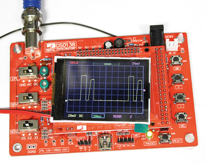
The DSO138 shows current drawn by a fuel injector.
The RGB LC display has a resolution of 320 x 240 (QVGA) with a screen diagonal of 2.4 " (6.1 cm). Some of the more expensive Desktop scopes have the same resolution with a much larger display, for my application the resolution is more than sufficient. Another bonus is that the complete schematic is included along with the unit. This makes it easy to add additional circuitry such as an external TTL trigger input. Power is supplied from a 9 V source and current consumption is around 100 mA. A simple voltage inverter chip produces a negative voltage from the positive voltage rail which is stabilized by a linear regulator. Another regulator supplies the 3.3 V for the STM32F103C8 which is an ARM Cortex A3 MCU from ST.
The MCU also contains a built-in fast ADC. It offers a resolution of 12 bits and an input voltage range of 0 to 3.3 V so that 1.65 V corresponds to the zero level on the display. The screen can be filled with even a relatively low-level input sine wave signal. Together with the high-resolution 12-bit ADC, this allows the introduction of an adjustable offset to the input signal. Unlike an analog input stage which would generally employ an analog voltage level to introduce an offset, here the offset is a digital value applied to the measured input signal value.
The relatively small ADC input range makes it susceptible to interference from other fast signals such as horizontal sync pulses. In an effort to reduce their influence I added some additional bypass capacitors to the supply rails but this wasn’t very successful. Despite the basic cost/performance rule which states: ‘You only get what you pay for’ this DSO module offers quite good performance at low cost as long as you are happy to put up with some minor niggles. If you like soldering, the DSO138 is also available in kit form at even lower cost. The kit comes with the SMD components already mounted to the board, you just need to solder a few through-hole components to finish the kit.

The DSO138 shows current drawn by a fuel injector.
DSO138
The picture shows the DSO138 module is a controller board which has a color LCD mounted on it. All control elements such as slide switches and push-buttons as well as sockets for signal input and the power supply are soldered to the board. On the left of the board, the choice of the input coupling and the amplitude adjustment can be selected with basic mechanical slide switches. Unfortunately, the quality of these switches (at least in my specimen) was a bit flaky so adjusting the gain often led to complete disappearance of the signal. The other functions are selected using buttons on the right. Overall the operation is fairly intuitive and works quite well.The RGB LC display has a resolution of 320 x 240 (QVGA) with a screen diagonal of 2.4 " (6.1 cm). Some of the more expensive Desktop scopes have the same resolution with a much larger display, for my application the resolution is more than sufficient. Another bonus is that the complete schematic is included along with the unit. This makes it easy to add additional circuitry such as an external TTL trigger input. Power is supplied from a 9 V source and current consumption is around 100 mA. A simple voltage inverter chip produces a negative voltage from the positive voltage rail which is stabilized by a linear regulator. Another regulator supplies the 3.3 V for the STM32F103C8 which is an ARM Cortex A3 MCU from ST.
Subscribe
Tag alert: Subscribe to the tag Test & Measurement and you will receive an e-mail as soon as a new item about it is published on our website! The MCU also contains a built-in fast ADC. It offers a resolution of 12 bits and an input voltage range of 0 to 3.3 V so that 1.65 V corresponds to the zero level on the display. The screen can be filled with even a relatively low-level input sine wave signal. Together with the high-resolution 12-bit ADC, this allows the introduction of an adjustable offset to the input signal. Unlike an analog input stage which would generally employ an analog voltage level to introduce an offset, here the offset is a digital value applied to the measured input signal value.
The relatively small ADC input range makes it susceptible to interference from other fast signals such as horizontal sync pulses. In an effort to reduce their influence I added some additional bypass capacitors to the supply rails but this wasn’t very successful. Despite the basic cost/performance rule which states: ‘You only get what you pay for’ this DSO module offers quite good performance at low cost as long as you are happy to put up with some minor niggles. If you like soldering, the DSO138 is also available in kit form at even lower cost. The kit comes with the SMD components already mounted to the board, you just need to solder a few through-hole components to finish the kit.
Read full article
Hide full article


Discussion (2 comments)