Review: Pulsar Labs Open Source Function Generator DIY Kit
on
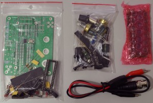 In this review we first describe the assembly of the module, because this is not dealt with in the supplied manual. The assembly should be fairly straightforward, even for those with little experience. There is no need to solder any SMD parts. It is important to check everything thoroughly before soldering the components. Of course we will share a few of our experiences of working with the module. In the photos we show the contents of the box, the components and the most important stages of the assembly process.
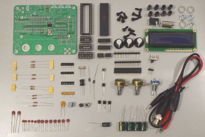
Assembly of the circuit board
As always, start with the lowest height components. The two SMD parts (U5 and X1) are already soldered to the circuit board. Begin with the ordinary resistors, the two diodes, resistor arrays and IC sockets. Follow that with the ceramic capacitors, TO-92 transistors and ICs, etc. Finally the potentiometers and the rotary encoder. Place crystal Y1 not completely down onto the circuit board, the metal housing could potentially cause a short circuit. Fit the 16-pin SIL socket for the LCD on the circuit board and solder the SIL header to the LCD. This is safer and prevents any inadvertent short circuits between the connections. To solder the SIL header to the LCD, first insert the SIL header into the socket and attach the LCD with screws and stand-offs to the circuit board. Then solder the pin header to the display. The socket and header are then perfectly positioned with respect to each other.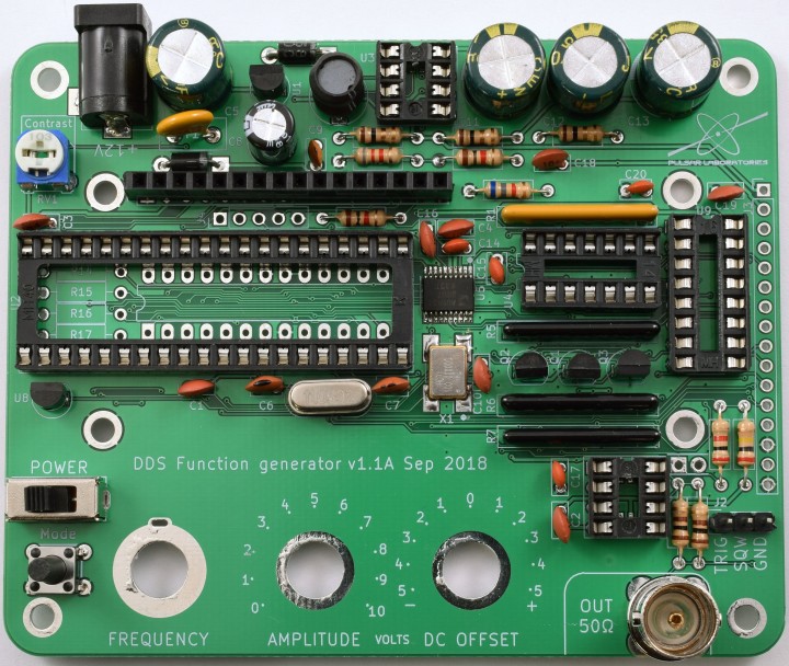
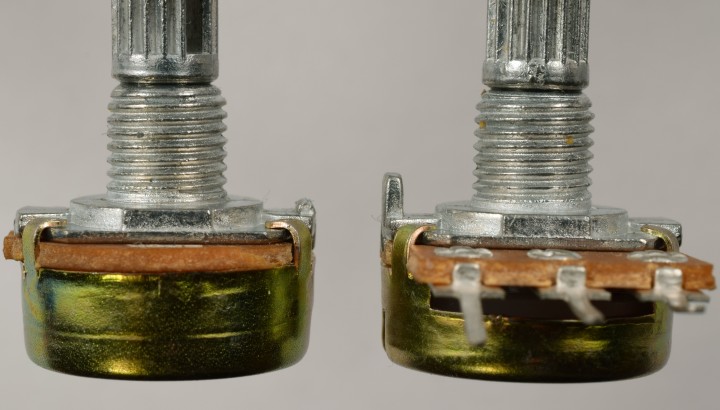
Finally the potentiometers and the rotary encoder are fitted. The potentiometers have a locating peg, but unfortunately this has not been taken into account on the circuit board. Cut this off using sturdy cutters.
The connection pins of the rotary encoder have to be bent 180 degrees, as can be seen in the photo below. The two connecting pins for the rotary push button have to be cut a little bit shorter, otherwise they stick out too far. Once the three rotary buttons are securely fastened and the connections are positioned on top of their respective pads, they can be soldered.
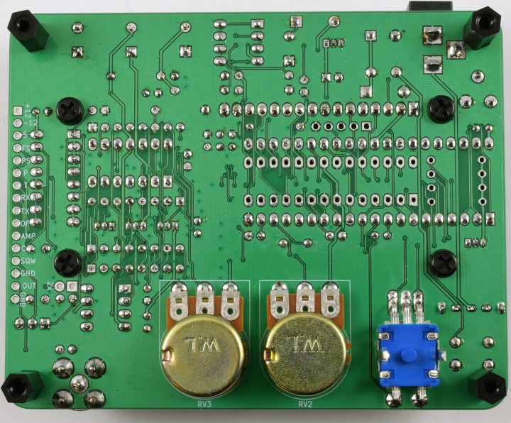
What caught our eye, is that J4 can be found on the circuit board (next to the microcontroller), but neither in the schematic nor among the parts. We did not fit pin header J3. The key cap for the Mode button is a loose fit, and is best held in place with a drop of glue. The 16-pin DIL header and socket are not mentioned in the BOM, but are nevertheless supplied. The 2-pin header next to U6 for the 2x offset is not supplied. A 1N4007 is missing from the parts, but instead a 1N5819 is supplied. The connections of L1 and C6/C7 have to be bent to suit the circuit board.


Discussion (0 comments)