

Review: Elektor/Make: Sand Clock Kit
February 16, 2017
on
on
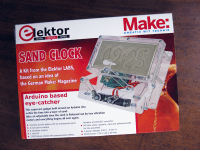 Described in the January & February 2017 edition of Elektor, the Sand Clock project, unique for its mechanical design, is all the better for its availability in kit form, which I’ve wanted to examine more closely in order to review it here. You’d have to be very jaded not to be seduced by the amusing principle of this gadget: to write the time in sand every minute, with a stylus on a pantograph and some servomotors, and erase it just before the next minute, and repeat endlessly. It is both clever and poetic.
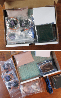 The attraction of such a project with its strong mechanical content rests in the various constraints (precision, simplicity, reproducibility, elegance etc.); the designer of the kit has resolved these problems very well. For the beginner maker, the construction of this kit and the study of the solution adopted will be very enlightening.
This seems to me a great way to occupy a rainy February afternoon!
Unpacking
The kit is presented in a box of which the size and weight are mainly due to the mechanical components, carefully packed with the PMMA (usually called Plexiglass™ or Perspex™) panels for the chassis, mini servomotors, mini vibrating motors, an assortment of bolts, nuts, washers, pins, spacers, adhesive pads and finally a packet of fine sand. On the electronics side, there is an Arduino R3 board, an Elektor shield partially assembled (SMDs mounted), a real time clock (RTC) and connectors for the servos, a USB cable, a 230 V – 9 V power supply and a button cell battery.Perfect presentation, but is there anything missing?
Read full article
Hide full article
Discussion (17 comments)
US2071124 8 years ago
US2071124 8 years ago
Hedwig 8 years ago
rjv 8 years ago
Before assembling the clock, try this method with only the servo,s attached to the shield.
Attach the shield PCB to the Arduino and connect the three servo motors. Make sure you attach
the servo motor connectors to the shield with the correct orientation. You can mark the servo
motor connectors with a small label if you wish. Connect the power supply to the Arduino and
connect the Arduino to a PC using the USB cable. Compile the sketch and send it to the Arduino
board.
When the sketch starts up, it first checks if there's valid calibration data in the EEPROM. When
there's no valid data, which is the case when the Arduino board is used for the first time in a sand
clock, the sketch drives all three servo motors in the middle position i.e. a pulse width of 1500 μs.
If you wish, you can check the position of the servo motors as follows: open the serial monitor in
the Arduino IDE, Select a non‐empty line ending, and send command svd. The response should
indicate all three servo motor channels have a pulse width of 1500 μs.
Turn off power, disconnect the servo motors and remove the shield from the Arduino.
Remember to label the servo,s as hight,left and right.if you mix them up, calibration wil be lost, and getting it right again will be a pain in the B...
rjv 8 years ago
after you completed the above procedure , you can assemble the clock and move on to the next calibration steps:1. Move the left servo motor to the vertical position (towards 1000 μs), e.g. svml 1080.
2. Store the setting: svslv.
3. Move the right servo motor to the vertical position (towards 2000 μs), e.g. svmr 2050.
4. Store the setting: svsrv.
5. Move the left servo motor to the horizontal position (towards 2000 μs), e.g. svml 1940.
6. Store the setting: svslh.
7. Move the left servo motor back to the vertical position using svml. You can query the correct
value with sed.
8. Move the right servo motor to the horizontal position (towards 1000 μs), e.g. svmr 1080.
9. Store the setting: svsrh.
10. Move pen up: svmp 2000.
11. Set pen position: ps 0 40.
12. Place the partially finished sand box on the supports and make sure it lies perfectly flat on all 4
supports. In case the sand box wiggles on the supports, twist it slightly diagonally until it lies
perfectly flat.
13. Move the pen servo motor to the down position (towards 1500 μs), e.g. svmp 1525. The
pantograph arms should be perfectly horizontal and the tip of the pen should hover
approximately 1 – 2 mm above the surface of the sand box. If necessary, mechanically adjust
the pen by screwing it up or down. Use the M4 nut to lock it in place.
14. Store the setting: svspd.
15. Check the pen down position in relation to the sand box:
* Pen position 1: ps 0 30.
* Pen position 2: ps 0 55.
Adjust the pen servo motor if needed.
16. Set the pen in a neutral position: ps 0 40.
17. Move the pen servo motor to the middle position (towards 1800 μs), e.g. svmp 1700. Make
sure the pen can't touch the sand.
18. Store the setting: svspm.
19. Move the pen servo motor to the top position (towards 2100 μs), e.g. svmp 2150. Move the
pen to highest position possible (servo horn in line with the acrylic lever).
20. Store the setting: svspu.
21. Set the vibration period (seconds), e.g. vms 5.
22. Review the settings with sed. Modify settings if needed. Note that start‐up program mode
should be set to command. Don't change the mode at this point.
23. Store settings in EEPROM: sew.
24. Set date and time in realtime clock, e.g. cw 2016 08 27 18 40 00. Note that a CR2032 battery
must be installed.
25. Check date and time with cr.
26. Lift pen up with plu.
27. Power off the sand clock.
now the calibration should be ok.
US2071124 8 years ago
US2071124 8 years ago
crlMIDI 8 years ago
I've made a zip file with all the information, but don't see how to post it to this project.
To get the times, I soldered a 6-conductor ribbon connector to the shield. The usual Arduino stackable headers are too tall, but if you haven't already started assembly, alternative plug-and-socket solutions can be found. The ribbon (and connectors I added for the tray) come out through a slot I cut in the back-plate.
Sketch sandclockBigBen.ino is a version with a few lines of added code that simply send the bytes for hours the the Arduino running BigBenIC2.ino. In response to sage, sketch sandclockBigBen15min.ino vibrates and writes in the sand only every 15 minutes (or whatever you want to program).
If I were to take this further, I'd add a permanent pretty time display, and as proposed above, some switches that let you turn the sandclock itself on only when you want to show it off. I haven't worked out how to extract the complete time data, nor how to take control using switches or a rotary encoder. We don't want to ask for anything that would increase the price, but the sand clock really needs some breakout and input facilities so people can do their own thing.
It would be fun to use a little xylophone and some actuators to do the chimes. More in the spirit of the project would be a single actuator that moves around the xylophone.
Finally, in response to comments above, a few years ago I bought plexiglass, polishing materiel and the special glues on the web (the supplier was plexiglas-shop.com).
sage 8 years ago
But after building it I find I can't live with the sound of it smoothing the sand every minute (or more if it has the bug previously mentined) especially if you plan to put it somewhere where people can see it - like in my living room. The sound is annoying. So, alas I have packed it up and put it away.
Question: How will we find out the results of troubleshooting the bug? I'd like to keep up with the bug fixes / improvements even though I'm not using it. Especially if a modification is made to eliminate the vibrators.
David Ashton 8 years ago
It's also easy to thread with a tap, so you could try this approach and use a locknut to hold the screw in place. I've also come to tears trying to use machine or self-tapping screws in plastics.
I assume any futher "fixes" or modifications will appear in the Err-lectronics column in the magazine?
US2071124 8 years ago
Thack 8 years ago
On mine, the holes in the sand box base plate are drilled slightly too big, so when you screw the machine screws in, they go in really easily and immediately strip the thread. I had to drill them out to 2.5mm and fit slightly longer machine screws with nuts on the bottom.
Secondly, the shaking system for the sand doesn't really work that well. I know that the author and/or Elektor have worked hard on it, but it still isn't sorted. Apart from it being way too noisy to leave the clock running, it often fails to smooth out the sand properly, and on mine the sand has a tendency to migrate to one end of the box.
Thirdly, despite following the calibration procedure to the letter, the numerals on my clock lean strongly to the left and get larger from left to right. I expect I can fix this by further tweaking of the calibration.
Fourthly, in previous projects using transparent plastic sheet, I found that any drilled hole which was under stress would produce fine cracks radiating outwards from the hole after a few, or several, months. I'm not convinced at all by the approach of forcing a machine screw to cut its own thread in the plastic. Of course, I may turn out to be wrong and am happy to eat humble pie on this if my fears are unfounded. As mentioned above, the amount of force needed to get those screws into the plastic is a bit scary at times.
Mine is one of the clocks which goes mad a few times an hour and redraws the time several times. It didn't occur to me that it might be a noise problem from the servos. I didn't think they generated much electrical noise, but I will go over it with a scope.
I'm working on a modification to make the sand shaking both quieter and more effective. I'll update this discussion with the results.
Despite all of the above, I still think this is an absolute cracker of a project - ingenious, amusing, and generally great fun.
Thack 8 years ago
I slightly enlarged the four holes in the base plate of the tray so that the springs will locate positively in them.
The sprung sand tray now has more freedom to vibrate up and down, which helps with the smoothing. I also put a blob of solder on each eccentric weight in order to increase the force of the vibration.
One thing to say: now that the tray doesn't rattle on the posts the smoothing cycle is MUCH quieter. In fact, this is probably the biggest benefit from the modification.
To be honest, even with the springs it still isn't great, but it is noticeably better and would be a trivial change to the "Mk 2" version of the kit. Personally I'm still looking at a different approach altogether and will report back with any new developments.
Thack 8 years ago
As contributor JLM7174 mentioned elsewhere, the software uses a constant value for L46 (called 'dist_46' in the software). However, L46 is not constant - it varies considerably with the position of the servos.
I think this must explain the distorted and left-leaning numerals when the clock is calibrated in accordance with the instructions.
I will try to fix this in the software and see what difference it makes.
Thack 8 years ago
The software correctly reflects the geometry as described on page 36 of Jan/Feb 2017 Elektor.
HOWEVER, the kit as supplied has an ambiguity in the instructions.
Look at the four levers which connect the pen to the servos. The two levers which fasten to the servos are interchangeable, although they need to be the right way up.
The other two levers are where the problem lies. The lever with the pen attached should go on the right hand side (when the clock is positioned with the servos nearest to you, and you are looking down on it).
If it's on the left, the numerals will come out distorted.
Thack 8 years ago
Occasionally mine will drive one of the servos right beyond the normal range of travel and jam up the levers. When this happens the only cure is to power down, move the servos by hand to within the normal range, and then power up again.
I'll run my oscilloscope over it as soon as I can to see if there is an electrical noise issue.
Thack 7 years ago
The instructions need a small change to make it clear which of the arms goes on which side.
The other problem is with the regular crashing (I'm assuming it's a crash) and reboot. Mine still has a "fit" every so often, writing the time several times in succession.