
SCR RELAYS SELECTOR
A simple but expandable and customizable microcontroller-free relays selector and driver circuit based on SCRs.
I needed to switch some loads, one at a time, in a simple and cheap way.
Thus this circuit that uses SCRs (Silicon Controlled Rectifier) as its main active components was born.
The relays are actuated by buttons but microcontrollers compatible inputs and a 5 V output to power external circuits are provided as well.
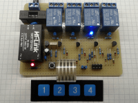
The whole circuit is powered by a small switching module HLK-PM01.
There is a power indicator red LED and a status blue LED for each relay and protection fuses.
If you need more relays just add more sections like the dashed line highlighted one visible in the schematic (you can also remove sections of course! Let at least one plus the Off button). The power relays can be replaced with signal relays, optocouplers, phototriacs or solid-state relays with minimal variations to the circuit.
The operation of the circuit is simple but not trivial. A SCR is normally triggered by a small gate current pulse, after which it can maintain the on state until the current flow passing through it is interrupted.
When you press a button the current required to trigger the SCR can reach the gate through its resistor but the charge variation of the capacitor C3 causes a short positive pulse on the base of the PNP transistor Q1 (normally kept in saturation state by resistor R3) which resets its collector current and the current through any other SCR which may be active as well. So only the SCR corresponding to the pressed button can be activated and switches the relay to the on state. The same happens if instead of pressing a button you provide an adequate voltage via an external input.
The SCRs used are of the kind "Sensitive Gate Trigger Current" and the transistor Q1 has been selected for the low drop of voltage Vce.
Looking for a free simulation software to better illustrate the operation of the circuit I found "Circuit Simulator" which allowed me to perfectly and easily verify the operation of this circuit. So I asked the author for permission to mention his very interesting and excellent work and put a link to its associated Web page. I think it's really worth to give it a go! http://www.falstad.com/circuit/circuitjs.html
Here's the link to a short video I made with the simulation of this circuit https://youtu.be/OC335jgW-YI (choose HD quality) and attached you find the schematic and some pictures of the prototype.
Best regards,
Anto
Thus this circuit that uses SCRs (Silicon Controlled Rectifier) as its main active components was born.
The relays are actuated by buttons but microcontrollers compatible inputs and a 5 V output to power external circuits are provided as well.
The whole circuit is powered by a small switching module HLK-PM01.
There is a power indicator red LED and a status blue LED for each relay and protection fuses.
If you need more relays just add more sections like the dashed line highlighted one visible in the schematic (you can also remove sections of course! Let at least one plus the Off button). The power relays can be replaced with signal relays, optocouplers, phototriacs or solid-state relays with minimal variations to the circuit.
The operation of the circuit is simple but not trivial. A SCR is normally triggered by a small gate current pulse, after which it can maintain the on state until the current flow passing through it is interrupted.
When you press a button the current required to trigger the SCR can reach the gate through its resistor but the charge variation of the capacitor C3 causes a short positive pulse on the base of the PNP transistor Q1 (normally kept in saturation state by resistor R3) which resets its collector current and the current through any other SCR which may be active as well. So only the SCR corresponding to the pressed button can be activated and switches the relay to the on state. The same happens if instead of pressing a button you provide an adequate voltage via an external input.
The SCRs used are of the kind "Sensitive Gate Trigger Current" and the transistor Q1 has been selected for the low drop of voltage Vce.
Looking for a free simulation software to better illustrate the operation of the circuit I found "Circuit Simulator" which allowed me to perfectly and easily verify the operation of this circuit. So I asked the author for permission to mention his very interesting and excellent work and put a link to its associated Web page. I think it's really worth to give it a go! http://www.falstad.com/circuit/circuitjs.html
Here's the link to a short video I made with the simulation of this circuit https://youtu.be/OC335jgW-YI (choose HD quality) and attached you find the schematic and some pictures of the prototype.
Best regards,
Anto
Discussion (2 comments)