

Simple digital timer
Simple digital timer as NE555 killer in many application were accurate timing is required from seconds until hours.
Simple digital timer
Not exactly a drop-in replacement for the good old NE555, but usefull for many timing jobs where a delay of seconds until hours is needed.
Original designed for a coffee-machine containing 3 NE555 timers for 3 different keys: cup, half pot, full pot. But the timer never came into production. Now, a couple of years later, I think the idea may be usefull for other hobbyists.
The main reason to replace the NE555 timers were incovenient calibration and because of electrolytics in the circuit the long-time stability was not so good.
The calibration procedure of the NE555 timer was as follows:
Development
I first started with a PIC16F84A, the type of microcontroller I used most often at that moment. For the coffee-machine 3 push-buttons were needed and a button to initialize the setup routine. Originally there were only 2 outputs: a flahing LED to signalize setup and the water-valve. Also the timers were locked against each other. To create a more universal timer now 3 outputs for the timers plus 1 for the LED are available and the timers became independent.
This prototype timer went into the source as version 3.
Later the real NE555 replacement was added: an 8-pin microcontroller with 1 timer. For stability a crystal can be used, but for a lot of application (as for the coffee machine) the internal oscillator is good enough. This became version 1.
But the 8-pin chip has 6 I/O-pins, therefore also 3 timers can be implemented in this small chip. This is version 2, which was originally designed as the target of my development.
Version 4 with max. 8 timers was created later when I looked at my simple PLC-board and thought a stand-alone board with 8 independent timers could be usefull, for instance for the modell-railroad. If you need more accuracy by using a crystal still 6 timers are available, but in that case you have to design your own board.
Summarizing: the 4 versions are:
1: PIC12F629/675:
2: PIC12F629/675:
3: PIC16F84:
4: PIC16F628A:
The source code is for all versions. To get the right one you only have to change the value of the define 'VERSION'.
Operation
In the main loop the inputs are monitored. Every change triggers TSTART for the specific timer. If a new interval has to be started the timing interval is copied to the RAM-area of this timer and the appropriate output is set.
Every timer uses 3 bytes in the EEPROM for the timing. These bytes can be filled by the programmer or by the setup routine.
Using a 4 MHz clock the interrupt routine is running continuously at 256 Hz. This routine checks the 3 byte counter for each timer which is decremented until it reaches zero. Then the end of the timing interval is reached and the output is reset.
Because the timers are independent you can start any timer at any time.
If the timer is switched on with the setup-input active it enters the setup-routine, indicated by the flashing LED. Now the timing can be programmed, 1 timer at the same time (see Setup). Beware that in versions 2 and 4 the setup key is combined with a timer key; if this is undesirable then don't use that timer! In my original version 2 design for the coffee machine only 1 output was needed for the water valve, so 2 additional ports were free for the setup key and LED.
By changing the program you can use any port to enter the calibration procedure (defines: 'REDLED' and 'PRG_PB').
The program is written in assembler (sorry for the inconvenience) because it had to run on the small 8-pin chip. But it is not very complicated. The most important jobs are done by 3 macros and quite a lot of things can be changed by defines.
By bits in a fourth EEPROM-cel for each timer you can change the behaviour:
Setup
Original description: place the cup or pot in the machine, select calibration-mode, press the required button and keep it pressed until the coffee-level is OK. Then release the button. Ready. Quite a lot more comfortable compared to the NE555
calibration procedure!
Moreover there are 2 ways to calibrate the timing:
Todo
Byte 4 (timer configuration) of the setup can only be changed using a programmer; it would be nice if this can also be done by a build-in setup routine.
Entering the setup by a standard timer-key is not very safe and the flashing of a standard timer-output can disturb a proces. Therefore the entering and signalizing of the setup could be improved for instance by using some inputs as temporary outputs.
For the time being: if the double usage of an input for setup and timer is a problem then do not use that timer!
Rewrite the whole program in a high-level language and use a more modern controller. This would simplify the addition of new options for anyone who does not speak assembler .
Not exactly a drop-in replacement for the good old NE555, but usefull for many timing jobs where a delay of seconds until hours is needed.
Original designed for a coffee-machine containing 3 NE555 timers for 3 different keys: cup, half pot, full pot. But the timer never came into production. Now, a couple of years later, I think the idea may be usefull for other hobbyists.
The main reason to replace the NE555 timers were incovenient calibration and because of electrolytics in the circuit the long-time stability was not so good.
The calibration procedure of the NE555 timer was as follows:
- place the cup or pot in the machine
- press the required button
- wait until finished
- if the coffee-level is not OK: turn the potmeter a bit
- repaeat the procedure until you are satisfied
Development
I first started with a PIC16F84A, the type of microcontroller I used most often at that moment. For the coffee-machine 3 push-buttons were needed and a button to initialize the setup routine. Originally there were only 2 outputs: a flahing LED to signalize setup and the water-valve. Also the timers were locked against each other. To create a more universal timer now 3 outputs for the timers plus 1 for the LED are available and the timers became independent.
This prototype timer went into the source as version 3.
Later the real NE555 replacement was added: an 8-pin microcontroller with 1 timer. For stability a crystal can be used, but for a lot of application (as for the coffee machine) the internal oscillator is good enough. This became version 1.
But the 8-pin chip has 6 I/O-pins, therefore also 3 timers can be implemented in this small chip. This is version 2, which was originally designed as the target of my development.
Version 4 with max. 8 timers was created later when I looked at my simple PLC-board and thought a stand-alone board with 8 independent timers could be usefull, for instance for the modell-railroad. If you need more accuracy by using a crystal still 6 timers are available, but in that case you have to design your own board.
Summarizing: the 4 versions are:
1: PIC12F629/675:
- the mini-version using an 8-pin chip
- 1 timer, crystal-osc. (or internal RC-osc.)
2: PIC12F629/675:
- meant for the coffee-machine
- 3 timers, internal RC-osc.
3: PIC16F84:
- the original prototype; in fact obsolete
- 4 timers, crystal-osc.
4: PIC16F628A:
- the max. version using my PLC-board (the most actual version)
- 6 timers, crystal-osc. or
- 8 timers, internal RC-osc.
The source code is for all versions. To get the right one you only have to change the value of the define 'VERSION'.
Operation
In the main loop the inputs are monitored. Every change triggers TSTART for the specific timer. If a new interval has to be started the timing interval is copied to the RAM-area of this timer and the appropriate output is set.
Every timer uses 3 bytes in the EEPROM for the timing. These bytes can be filled by the programmer or by the setup routine.
Using a 4 MHz clock the interrupt routine is running continuously at 256 Hz. This routine checks the 3 byte counter for each timer which is decremented until it reaches zero. Then the end of the timing interval is reached and the output is reset.
Because the timers are independent you can start any timer at any time.
If the timer is switched on with the setup-input active it enters the setup-routine, indicated by the flashing LED. Now the timing can be programmed, 1 timer at the same time (see Setup). Beware that in versions 2 and 4 the setup key is combined with a timer key; if this is undesirable then don't use that timer! In my original version 2 design for the coffee machine only 1 output was needed for the water valve, so 2 additional ports were free for the setup key and LED.
By changing the program you can use any port to enter the calibration procedure (defines: 'REDLED' and 'PRG_PB').
The program is written in assembler (sorry for the inconvenience) because it had to run on the small 8-pin chip. But it is not very complicated. The most important jobs are done by 3 macros and quite a lot of things can be changed by defines.
By bits in a fourth EEPROM-cel for each timer you can change the behaviour:
- retriggerable or not
- edge or level triggered
- immediate output or delayed pulse
- length of the delayed pulse (1/256 sec., 1/16 .. 15/16 sec. or 1 .. 15 sec.)
Setup
Original description: place the cup or pot in the machine, select calibration-mode, press the required button and keep it pressed until the coffee-level is OK. Then release the button. Ready. Quite a lot more comfortable compared to the NE555
calibration procedure!
Moreover there are 2 ways to calibrate the timing:
- keep the button pressed until end of interval (convenient for short periods)
- press the button a short time to start and press again to end the interval
Todo
Byte 4 (timer configuration) of the setup can only be changed using a programmer; it would be nice if this can also be done by a build-in setup routine.
Entering the setup by a standard timer-key is not very safe and the flashing of a standard timer-output can disturb a proces. Therefore the entering and signalizing of the setup could be improved for instance by using some inputs as temporary outputs.
For the time being: if the double usage of an input for setup and timer is a problem then do not use that timer!
Rewrite the whole program in a high-level language and use a more modern controller. This would simplify the addition of new options for anyone who does not speak assembler .
Updates from the author
robvh 2 years ago
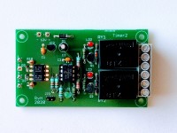
The program has been expanded with version 6 of the hardware, which is this PCB. Operation is equal to other versions.
Timer_uni.zip (10kb)
timer_uni.pdf (17kb)
timer-uni.jpg (602kb)
PCB1840_tim_brd.pdf (18kb)
robvh 6 years ago
A simple change which saves 165 words of flash and use 1 (one) additional byte of RAM for the pointer.
Not bad and a lot of saving for such a small device.
robvh 6 years ago
The program for the timer with display is in principle ready as well, but does not fit into the 16F628a (need more program memory; the 16F648a will do). Because I am not happy with the code (usage of goto's because of the stack depth of the PIC and tricks to keep it compact), I will not publish the program.
ClemensValens 6 years ago
typedef struct {
uns8 Fst; // Seconds parts
uns8 Sec; // Seconds
uns8 Min; // Minutes
uns8 Hrs; // Hours
} TimerxTime;
typedef struct {
uns8 Config; // Timing program 0..12
TimerxTime Timer;
TimerxTime Delay;
} Timerx;
or
typedef struct {
uns8 Config; // Timing program 0..12
TimerxTime TimerDelay[2];
} Timerx;
This would allow you to reuse code by passing it a TimerxTime struct (or pointer to it) instead of referencing the Timerxxx and Delayxxx variables explicitely as is now done in f.i. the function TiRun.
robvh 6 years ago
I also changed the storage of the preset times from 3 bit with an LSB of 1/256 second to 4 bytes (1/100 sec., seconds, minutes, hours). This makes presetting the timers by directly programming the EEPROM a lot simpler. Additionally the maximum time increased from 18 hours to 256 hours (more than 1.5 week). The timing-programs have not been changed.
The timer has been build using a PCB wich I created for simple projects like this; it contains the electronics for a microcontroller and an LCD-display and a prototyping area for the rest of the circuit.
The timer is running on 12 VDC and the outputs are connected to 3 relais. For the programming of the timer a rotary encoder, 3 switches and an LED are connected to X1.
To start the programming mode press SW1, the switch on the rotary encoder; then press S2, S3 or S4 without releasing SW1 to select the required timer. The display will show the result on the top line. On the bottom line you see "Prog Tact Tdel". With S2, S3 or S4 you can select the parameter to change. If you select "Prog" the program number can be chosen with the encoder. If you select "Tact" of "Tdel" the timing can be programmed. On the topline you will see something like "T2 Hrs Min Sec". Pressing S2 and simultanuously rotating the encoder changes the hours. With S3 the minutes are changed, with S4 the seonds. You can also use the timer2 input to setup the time as in the timers without display (teach mode; the timer will simply reproduce the time you "teached" with its input).
The program sees if an LCD is connected; without display the timer behaves like a simple triple timer without the setup option.
Source and hex file for the PIC16F628a microcontroller (46kb)
robvh 7 years ago
No need to make your own PCB. See schematic.
Use version 4 of the software for this setup.
robvh 7 years ago
The new version of the software was created because my first requirement was not met by the previous versions. I wanted a multi-function timerchip which (once burned into the chip) can completely be setup without a programmer. With this new software release that goal is reached.
The program is still written in assembly-language; no way to use the C-language for the microcontrollers involved. There simply is not enough memory.
2. Versions
There are 5 versions of the program for some different configurations:
- 8 pin chip (PIC12F629/675), 1 timer, crystal (or internal) oscillator
- 8 pin chip (PIC12F629/675), 2 timers, internal oscillator
- original version with PIC16F84A, 5 timers, crystal oscillator
- maximum version with PIC16F628A, 7 timers, internal oscillator
- improved version 3 with PIC16F628A, 6 timers, crystal (or internal) oscillator
Versions 1 and 2 have the NE555 footprint but with a lot more possibilities. The only limitation is the power supply voltage of 5V compared with 3 .. 15 V for the NE555.Version 3 is only created because I had some 16F84A lying around. If you have to buy the chip then use version 4 or 5. The 16F628A is better and a lot cheaper!
I included the hex-files for these 5 versions, so you can program them immediately into a microcontroller of the correct type.
3. Timer modes
3.1. Basic configuration
Internally the operation of the timers is controlled by configuration-bits. To simplify the user-interface some usefull functions are defined as a table of bitmasks. You can eventually define other combinations (no guarantee all will work; I only tested the 12 defined ones) or delete unwanted ones.
The cycle of any timer is always the same:
- start delay (if present)
- output on (after delay or immediately)
- start timer (if present) after delay or on rising or falling edge of input
- output off
Every step in the cycle is controlled by one or two bits in the bitmask.3.2 Bitmask definition
Following bits are used to define timer operation (still 1 left for new nice functions!):
bit7+6 - Timer (00=none, 01=interruptable, 10=single shot, 11=retriggerable)
bit5+4 - Delay (00=none, 01=interruptable, 10=single shot, 11=retriggerable)
bit3 - Trigger timer (0=rising edge/timeout/after delay, 1=falling edge/streched input)
bit2 - Toggle (0=no, 1=falling edges neglected; 2nd rising edge functions as falling edge)
bit1 - Astable operation (free running if timer input is active)
bit0 - Inverted input signal
3.3 Predefined modes
Following combinations are actually defined within the program:
0 basic timer B'10000000'
1 retrigerable timer B'11000000' (hallway lighting)
2 streched input pulse B'10001000' (door entry actuator)
3 basic timer, inverted input B'10000001'
4 delayed timer B'10100000' (modell railway: train waiting)
5 retrigerable delayed timer B'10110000' (watchdog function)
6 toggle B'00000100' (press on, press off)
7 toggle with timeout B'01000100' (hallway lighting)
8 delayed mirror B'00010000' (detect too long pulses)
9 delayed streched mirror B'10011000' (delayed on, delayed off: bathroom fan)
10 mirror with timeout B'01000000' (limit switch-on time)
11 streched toggle B'10001100'
12 astable multivibrator B'10100010' gated by timer input
Timing diagrams of all combinations can be found on the included pdf-file.
4. Setup
A separate input with a pushbutton is used for setup. Setup mode is entered by switching on the power with the pushbutton pressed. If it is released the LED shows one short flash every second. The next stages in programming are reached by pressing the button one or two times. Stage 2 shows 2 short flashes every second, stage 3 shows 3 flashes. The next keypress will bring you back to stage 1.
The setup is stored in EEPROM, safe from power-interruptions.
If setup is ready switch off the timer and switch it on again without the button pressed.
4.1 Programming timer duration
This is stage 1.
Press the key of the timer to be programmed; the output of the timer is activated.
Release the key as soon as the required time has finished.
Or to be able to program longer intervals you can:
Press the key of the timer to be programmed for less than 0,5 sec.; the output of the timer is activated.
Press the key a second time as soon as the required time has finished.
4.2 Programming delay time
This is stage 2.
The operation is equal to programming the timer duration.
4.3 Programming timer mode
This is stage 3.
Press key of timer to be programmed.
Timer will now go to mode zero (indicated by active output of the timer involved).
Press the timer key as many times as needed.
After 12 key-presses (depending on the table-length) the counter becomes zero again.
There is no other indication except the active output showing mode zero; for the rest you will have to count your keypresses.
4.4 Programming directly into EEPROM
By using a programmer you can directly store the timer setup into the chip. This was in fact not the intention of the project, but if you know exactly the required setup or if you need a number of equal chips this is an alternative. See source file for EEPROM layout.
5. Additional comment
Maximum timer duration and delay time is over 18 hours (65536 seconds) with a resolution of 1/256 second.
By adding a 4th byte to the timers and their setup you could also increase the max. time by a factor of 256. In that case a bit more programming is needed (but not very much). The necessary changes are marked in the source, but not tested.
The resolution of the timer will stay the same. Max. time will increase to 4660 hours (assuming no power loss etc.), which is over half a year. Don't try this with an NE555! By the way: no idea how to push a switch for so long time to setup the timer, but you can program your timing values using a PIC-programmer.
example schematics for all 5 versions (105kb)
schematic explanation of timer modes (17kb)
Version 4 timer on the simple PLC-board (27kb)