

Simple Dual Voltage Bench Power Supply
This compact dual power supply is intended for general use on an electronic workbench. It has few distinguishing features apart from being easy to make, compact and is constructed from readily available SMD components. The circuit design is taken from manufacturer’s application notes with minor embellishments. It has been designed to have outputs of 0 to +/- 15 volts (dual tracking) with a nominal output current of 250mA.
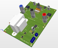
As you can see from the circuit diagram, 'Dual Variable PSU.pdf', it is simple and based upon two adjustable linear voltage regulators, an LM317 and the negative LM337 regulator both adjusted via a dual potentiometer. The circuit features a smattering of protection diodes to guard against transients. It also has biasing circuits which minimise the effect of the 1.25V control voltage required by the regulator chips. Normally, circuits of this type would not achieve a zero-output voltage but, using the forward volt drop of two diodes in both the positive and negative adjustment circuits, this problem is mainly overcome.
In addition to the circuit diagram, I have produced a detailed BOM, PCB design and all of the Gerber files required to order the components and build this circuit. To simplify the final assembly, and to produce a compact design, the Potentiometer and power output sockets have been employed to mount the PCB on the front panel. Please see the full description in 'Dual Bench Power Supply.pdf'' in the 'OTHER' Section.
In addition to the circuit diagram, I have produced a detailed BOM, PCB design and all of the Gerber files required to order the components and build this circuit. To simplify the final assembly, and to produce a compact design, the Potentiometer and power output sockets have been employed to mount the PCB on the front panel. Please see the full description in 'Dual Bench Power Supply.pdf'' in the 'OTHER' Section.
Discussion (3 comments)
Michael Moser 1 year ago
J.F. Simon, Elektor 1 year ago
DE183144 1 year ago
The regulator needs a minimum load of typical 3,5mA or max 10mA for
good load regutation (table 7.5 electrical characteristics) - thats the reason for
the 240 Ohm (LM317) and the 120Ohm (LM337) in the datasheet schematics.
Does onyone have experience when using the regulators this kind out of spec?
Armin.G 2 years ago
But for many applications a bit weak in power.
Another point is that the temperature coefficiant of the "pull-down" diodes goes to the output voltage.
And one has to choose a good potenziometer with symmetric linearity to keep both voltages equal.
With an additional op amp it's possible to control both voltages with one potmeter.
Greets
Armin