

SKIP!! (single button Media Player control via USB)
At home we ripped all our audio CDs to a NAS and most of the time we use Windows Media Player or VLC player (we still don’t agree which one’s the best) in random order play to have some background music in our workshop.
We found a better solution in a robust industry-standard emergency stop button I once bought on a flea market for just 1 Euro (okay, these are really expensive when you buy a new one!), in combination with a small ATtiny85 board that translated a key press into USB HID Media Control code ‘next track’. But there was still a (long) cable between this button and the PC, waiting for time, mood and inspiration to make a more practical wireless version. The idea was triggered again when I worked on the wireless quiz button project in the Elektor Lab, with its nice and small battery powered nRF24L01 transmitter boards. Easy to handle with available Arduino libraries, the only thing missing was the bridge between an nRF24L01 receiver and USB (consumer) HID to instruct the media player software to skip to the next track. Around the same time I found Nico Hood’s Arduino Hoodloader project on the internet which seemed nice to experiment with, and so the wireless Skip Button was finally made. The first version was built with an Arduino Uno plus an ELPB-NG prototyping shield. Not the smallest and most elegant solution, but it was fun to build it with an Arduino Uno board that was only collecting dust.
The Arduino Uno needs no further introduction, since its release way back in 2005 there have been numerous successors based on the original concept. It does have a USB-connector, but this is only intended for programming, power supply and UART connection to a computer, not for real USB-based applications. Few people realise that there is a second microcontroller on the board, that mainly serves as a UART <-> USB bridge between the ATMEGA328 (and its bootloader) and Windows/Linux/Apple computer. This chip –an ATMEGA16U2 on most Arduino Uno boards- is also programmable via USB with special utility programs like Atmel’s Flip and even has its own on-board ISP connector for flashing its firmware. There were already other firmware versions for this chip available that added USB (mostly HID) functionality to the Uno, but the downside was that the user had to revert this firmware to the original serial-USB version in order be able to (re)program the 328 via the Arduino IDE.
Nico Hood developed the Hoodloader, a special bootloader for the 16U2 that contains a USB stack and that can also switch back to ‘normal Arduino mode’. Simply put: with the Hoodloader your original Arduino Uno turns into a board with two independent microcontrollers that can both be programmed from the same IDE. The ATmega328 serves as I/O-microcontroller (the ‘original Arduino), while the ATmega16U2 contains the USB functionality. Both can run their own sketches, with the only –possible- interaction via the two-line UART connection between the microcontrollers. Sounds great and easy, but I must admit that it took me some time to find out how to work with this enhanced Arduino Uno concept in the Arduino IDE. Furthermore, the microcontrollers both have a sketch running, and the user must implement some kind of protocol to let the two communicate. For my application I used the aforementioned UART connection between the 328 end the 16U2. The ATmega328 runs a sketch that listens to an nRF24L01 receiver and simply sends a byte over the on-board serial connection to the 16U2 when a valid signal from the wireless button is received. The 16U2 listens to its serial input and sends the corresponding ‘next track’ USB package to the computer/media player software. Please note that the ATmega16U2 (possibly) can handle this application on its own, it can interface directly with the nRF24L01 and doesn’t really need help from the ATmega328. The 16U2’s SPI pins are accessible on its ISP-header and some additional I/O pins are connected to solder pads next to this connector. But here I just used this idea to play with the Hoodloader, to see how to work with two sketches running on an Arduino. And of course: a small ATmega16u2-board that fits inside a standard USB-stick case is under construction now…
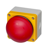
There is much more to tell and to know about the Hoodloader project than the simple application presented here, but this may help as a starter. Please refer to https://github.com/NicoHood/HoodLoader2 for more information. For the transmitter -the real Skip Button- we used the design of the Wireless Quiz Button (see https://www.elektormagazine.com/labs/wireless-quiz-buttons-150499-i), we just took the red button from this project without any changes in hardware or software.
Discussion (2 comments)


anto 9 years ago
Hi Luc,
I'm the Wireless Quiz Button's author and I'm happy to have helped inspiring the Skip button's idea!
I found the Hoodloader project very interesting and I wanted to make this very nice application.
Unfortunately I don't have an Arduino One board (never had one!) so, while thinking about how to simply send the USB HID Media Control code ‘next track’, I remembered the software-only implementation of a low-speed USB device for Atmel’s micros called V-USB (https://www.obdev.at/products/vusb/index.html).
After some research I found the Adafruit's project 'Pro Trinket Rotary Encoder' which implements a USB HID Consumer Devices class, which is able to manage multimedia keys and thus the following command 'MMKEY_SCAN_NEXT_TRACK 0xB5' (https://learn.adafruit.com/pro-trinket-rotary-encoder).
Although this project regards the Trinket Pro board, it works perfectly with the stand-alone Atmega328P-PU micro, loading the Adafruit's Trinket boards (via board manager) to the Arduino IDE 1.6.6, selecting the correct board and loading the code via USBasp.
As a consequence, merging the (simplified) Wireless Button Quiz receiver code and the Adafruit's multimedia control library, I got a 'Skip Button Receiver' tested on Windows 7, 8.1, 10, with just a few components I already had!
So now I can happily walk around at home with my Skip button! ;-)
Best regards,
Anto

Updates from the author
Lucky 8 years ago
The skip button on the Arduino was a nice exercise to work with the Hoodloader and create a USB HID device without extensive programming. But as I said before: this solution is too bulky and it’s absolutely overkill to use two processors: the ATmega16U2 for the USB-interfacing and the ATmega328 for handling I/O. The 16U2 can do this task on its own, so we designed a small PCB that fits into a USB-stick case, carrying the processor and the nRF24L01.
Most of the schematic is a copy of the Arduino Uno 16U2-part (never change a winning team): the USB interface, the processor plus oscillator, EMC-, overcurrent and ESD-protection.
The power supply is taken from the USB interface, its 5V is connected to UVCC, the input of the 16U2’s internal 3.3V regulator (no additional voltage regulator needed). Its output (UCAP) is connected to the VCC and AVCC input pins of the processor, and it is also feeds the 3.3V supply voltage of the NRF24L01. Note the 10uF capacitor on the radio module’s power supply, this is absolutely necessary to ensure proper operation.
In the current sketch LED1 will blink three times on power up to show that the application is running. After that it wil blinks once when a valid command is received from the transmitter.
And that’s about all we need to implement the Media Player controller, a bit more elegant solution than the nRF24L01 on a shield on top of an Arduino board. The Hoodloader firmware in programmed into the ATmega16U2, and we only need a few lines of code in an Arduino sketch to make the skip button work. In fact, we can change this sketch to make a more complete Media Player controller, e.q. execute another command like Mute or Pause if the button is pressed longer than –let’s say- 1 second. But let’s not forget the initial goal of this project: one huge button that can not be missed when we want to skip to the next music track. But feel free to use this PCB to develop your own wireless USB HID device, and please let us know what application you built with it!
Programming the Hoodloader (or other) firmware
If you build this board from scratch, you will probably have a new 16U2 processor that has its factory-programmed bootloader which allows the user to program their own application via the USB port, using a PC programming utility like Atmel’s Flip. Or maybe there will be an important update of the Hoodloader, or -for some reason- you want to reprogram the microcontroller.
Unfortunately you can’t use the 16U2’s USB interface to (re)program the Hoodloader firmware. You’ll need a parallel programmer with a 32-pin ZIF socket (which most of you probably don’t have!) or some AVRISP-like programmer (much more affordable and probably present in many labs). Our tiny USB-stick board doesn’t have the standard 6-pin AVRISP connector, but all programming signals needed are present on the connector for the nRF24L01 board, except for the reset line. That’s why we put the extra reset pin next to this connector, you can use a standard 10-pin 100 mil pitch connector, a bread board or veroboard to connect your AVRISP to the board (use the connection diagram attached to this posting) and program the Hoodloader firmware into the 16U2. Don’t forget to use the correct fuse settings! (HoodLoader2 Fuses: low_fuses=0xEF high_fuses=0xD8 (boot to Bootloader) extended_fuses=0xFC (no HWBE) unlock_bits=0x3F lock_bits=0x0F)
The PCB is designed to fit into a Strapubox USB1 case. Space is a bit tight, so there are some things to consider when assembling the PCB. First solder all components except for the radio module and then -if necessary- program the Hoodloader firmware. In order to do so, you'll have to solder a pin header on the board, or just some pins or wires to make a connection to an AVRISP programmer. Remember that these connections need to be removed afterwards to accomodate the nRF24L01 receiver, so make sure they can be easily desoldered. The 5V power supply can be connected to the USB-connector K1 (just connect it to a USB port of your computer). Program the firmware, disconnect the programmer and unplug K1 and plug it in again. If all is well you'll see the PC installing the correct USB-driver, in Windows' Device Manager it should appear as a COM port named Hoodloader or similar. If not, recheck the fuse settings and reprogram the ATmega16U2.
The board now is just like an Arduino Uno (with Hoodloader in stead of the standard bootloader) but without the ATmega328 microcontroller. It will be recognised in the Arduino's IDE, just like in our previous version with the Arduino Uno board. But now we only need to program one sketch: Skip_button_6u2_only.ino (contained in download 150650-12 USB stick.zip). Then unplug and plug K1 again and then the board will report itself as 'HID-compliant consumer control device' in the Device Manager.
Now the Hoodloader and the skip button sketch are both up and running, unplug K1 and remove the pins/wiring you installed for connecting the AVRISP programmer.
Take the nRF24L01 receiver, desolder its crystal from the top side and solder it to the bottom side of the radio module's PCB. Now mount the receiver board on top of the 16U2 board, the crystal resting on the surface of this PCB. Make sure the two boards are parallel and as close to each other as possible before soldering the connector of MOD1. Use a flush cutter to remove as much as possible of this connector's pins, and put the assembled PCB into the Strapubox case. N
Schematic of the USB-stick receiver (174kb)
USB stick receiver Bill Of Materials (18kb)
Arduino sketch (1kb)
150650-1-elektor-pcb-ready.jpg (98kb)
Prototype with Strapubox USB case (646kb)