

Small Circuits Revival — Episode 2
on
Energy Efficient Relay
From an idea by Michael A. Shustov (Russia) and Andrey M. Shustov (Germany)
Version 2
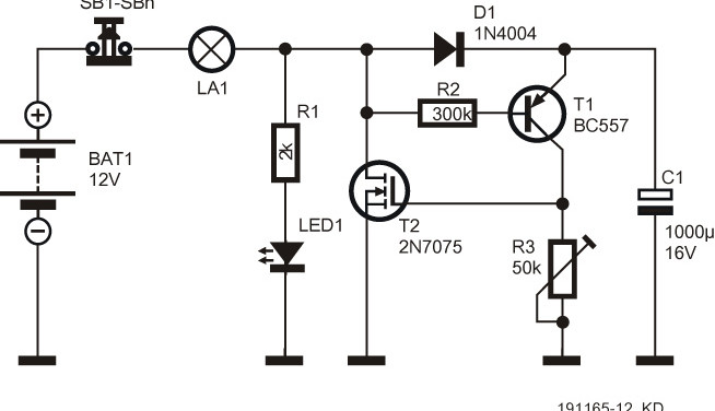
In this version (Figure 1), the electromechanical relay got replaced by a MOSFET type 2N7075 or 2N7085 as the switching element. Important: in contrast to the previous incarnation, the ‘lights-on’ time can be conveniently set using preset or potentiometer R3. Roughly speaking, 1 kΩ corresponds to 1 second, so with the value of 50 kΩ shown in the diagram, an adjustment range of 1 to 50 seconds is achieved.
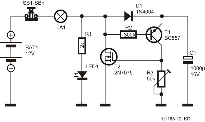
The big advantage of the relayless version is that a much smaller capacitor can be used in position C1. This improves the repeatability of the circuit. The maximum current that can be switched (with sufficient cooling) is about 30 A for the 2N7075 and 20 A for the 2N7085.
Again, this version is only suitable for low-voltage direct-current applications, and should never be used for lamps connected to the AC line voltage.
Miniature switches with push-to-break action (i.e. normally-closed types) are easily available. Mains-rated switches with the same functionality are rare but they do exist - just put Google to work with the search term "impulse switch"... They might come in handy with the mains-operated version we'll be looking at next week!
Correction
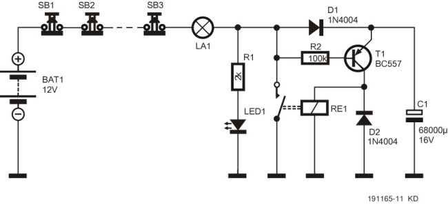
Several readers have (rightly) pointed out to us that in the schematic of the first version published in Episode 1 has an error: flyback diode D2 has ended up in the wrong place. Our apologies, of course, and thanks to the attentive readers! Below is the corrected schematic (Figure 2).
Discussion (2 comments)
Johann Scheepers 5 years ago
Tattik 5 years ago