Small Circuits Revival (23): Energy-efficient Relay
on
Energy-efficient Relay
idea: Friedrich Lischeck (Germany)
The big disadvantage of the energy-efficient relay that was described in Episode 1 is that it requires pushbuttons with a normally closed (n.c.) contact. These are sometimes difficult to obtain, and most hobbyists are not likely to have these on hand.
The small but clever circuit that we will take a look at now employs normal pushbuttons (i.e. n.o. , normallly open with a momentary contact) and a standard 5-V monostable relay with two (changeover) contacts – see Figure 1.

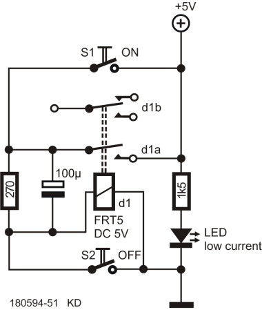
To make this possible, one of the pair of contacts in the relay is used for this; it is not difficult to figure out the operation of the circuit. The relay coil is energized after pushing S1; both contacts pull in – and the relay coil remains energized via one of the relay contacts and a 270 Ω resistor. Because of the big electrolytic capacitor, which acts as a short circuit at the moment of switch on, the initial energizing current through the relay exceeds the holding current in the energized state.
To switch the relay off it is sufficient to push S2: the relay coil is short-circuited; the relay drops out and the rest state is restored.
The LED indicates whether the circuit is ready to operate. A nice detail is that the relay does not close the instant that the power supply voltage is applied; this does require an actual push on S1. And should someone come up with the idea of pushing both buttons at the same time: not a problem, nothing happens because S2 has priority.
Discussion (6 comments)
Arie 4 years ago
Chris White 4 years ago
To be honest, at 5 volts there isn't going to be a problem unless a spike makes it out of the switch circuits and into sensitive electronics. But it's stll good practice to watch your reactant components and supply proper power-down discharge paths.
Arie 4 years ago
In the active state, d1a is closed, the voltage over the 100uF is about 3V. When S2 is pressed the voltage on the 100uF almost immediately rises to 5V, so a jump of 2V. The charging current spike is only limited by the series resistance in the circuit PSU - d1A - 100uF - S2 - PSU. With a typical series resistance of just milliohms this high current spike can damage S2 and the d1a contact.
Chris White 4 years ago
The original article states a coil resistance of 1050 ohms. If I'm seeing this right, the effective circuit during operation is +5v, thru d1a, thru the resistor / capacitor parallel, thru the coil to ground. Due to the zero effective resistance of the capacitor at initial turn on, the relay easily gets the voltage it needs to pull in. Inrush current is limited by the coil's initial high impedance. At steady state we have 5 volts / (270+1050) = 3.79 mA. The voltage dropped by the coil should be 3.79 x 1050 = 3.98 volts.
I'm tempted to make this circuit just to put an oscilloscope probe on the negative side of the capacitor. It'd be interesting to see just how fast it charges when S2 closes, and to see the effect of the relay coil field collapse on it, if it's slow enough to be visible.
I'm not an amateur, but I am a bit rusty at dynamic circuit analysis, so please correct me if I have anything wrong. Just prior to the pressing S2, the capacitor would be holding the same voltage as the resistor drop, about 1.2 volts. When S2 closes, before d1a opens, the full five volts is dropped across both capacitor and resistor, charging the capacitor extremely quickly with an extra 3.8 volts. I submit the possibility of the dampened coil discharge slowing the release of d1a until the capacitor was close to, if not at, full charge. Since the damage you're referring to would be due to opening during high current, d1a is probably safe. The same can't be said about S2, which closed with 3.8 volts across it. As soon as d1a opens, both sides of S2 are at ground potential.
Is that close to being right?
Arie 4 years ago
The problem I noted has nothing to do with coil current or voltage, only with the 100uF capacitor. The damage to S2 is done when it closes (as you wrote: "charging the capacitor extremely quickly" which can only be done by a high current). The current spike through the 100uF when the contact CLOSES (with an initially small surface area) damages the contact plating. See the datasheets for the rating of typical small switches. My suggested 22 Ohm resistor limits the current spike to a safe value. The voltage on the coil with S2 closed will be below the minimum drop-out rating of the FTR5 relay. Please check the datasheets, don't assume anything.
f4dui 4 years ago
F4dui