

Small Circuits Revival – Episode 4
on
Automatic Gain Control
idea: Ton Giesberts (Elektor Labs)
An automatic gain control circuit (AGC) is very useful in many applications; an example is the detection of weak signals. One application you could think of is a bat detector, where the sounds (ultrasonic) picked up by the microphone are first amplified before shifting into a range that is audible by humans. That such an AGC does not need to be complicated is demonstrated by this circuit.
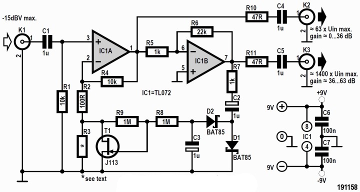
It is intuitive to use one or more opamps, such as sketched in Figure 1. A non-inverting amplifier is built around IC1A. For the gain A1 the following holds:
A1 = R4 / (R2 + R3||T1) + 1
On the other hand, IC1B is configured as an inverting amplifier: the gain A2 is given by:
A2 = –R6 / R5
The ‘trick’ of this circuit is in the two diodes D1 and D2; together with capacitors C2 and C3 these form a cascade circuit (voltage doubler). These are used to generate a control voltage from the output voltage of IC1B that is subsequently used to control the amount that JFET T1 conducts.
As is well known, a JFET is great as a variable resistor. Resistor R3 in parallel with the JFET can be used to set the minimum gain for IC1A.
In the circuit as it is sketched in Figure 1, we used a J113 for the JFET; the two diodes are both Schottky types. However, you are not necessarily required to use these exact same parts; the circuit will also function with other JFETs, and you can also use ordinary diodes, such as 1N4148, for D1 and D2.
The assembly is not particularly critical – a real circuit board is not necessary to begin with, a breadboard will work fine. The circuit therefore invites experimentation!
In the March & April 2020 issue of ElektorLabs Magazine we will delve a little deeper into this quite interesting circuit.
Discussion (3 comments)
bluesbreaker 5 years ago
Chris-H 5 years ago
It's also quite easy to make this circuit for a single-rail supply, with the addition of a couple of biasing resistors - I use a similar circuit to this - with a unity gain FET input buffer - as a superb guitar compressor. The time constants are a little different from this circuit, but it's essentially the same. I have less gain in the first op-amp and more in the second - I don't need massive audio gain (and the attendant noise) that would have to be attenuated at the output.
I find that the LM358 is a good cheap choice for the single-rail version, as it can swing to the rails and recovers from overload withouot latching up!
bluesbreaker 5 years ago