SMD soldering by hand

It is possible to solder SMD components by hand.
Yes, it is possible to solder SMD components on a breadboard with a little care.
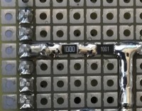
I would like to show you a circuit that I have recently assembled. It can be seen 1206-sized SMD diodes and resistors, as well as some little larger capacitors.
The technique consists of placing the component centered on the insulating gap between two pads. It is convenient to have a third hand to hold it, or in its absence, a self-closing clamp. After soldering the first side, the clamp can be removed and the other side can be easily soldered hereafter.
Previously, the layout of the components must be carefully planned. I use graph paper, pencil and rubber. Each intersection represents a breadboard drill. You just have to draw the components and the tracks to connect them. And erase and repeat several times, of course.
I include some images to better show the process:
1. Study for the components layout
2. How to hold the component to solder
3. Solder side, SMD components already soldered
4. Solder side, adding wires that cannot be made with solder
5. Components side. It can be seen that there are hardly any passive components, since they are on the other side.
This method requires good vision, steady hand and a little effort, but in return, allows more rational distribution of the components and a greater density of them than with the use of traditional 1/4 W resistors


Discussion (4 comments)
mfc 4 years ago
Mike Cowlishaw
http://speleotrove.com/mfc/
smt-pcb-0007.jpg (304kb)
jo6466 5 years ago
Toutes mes réalisations sont faites ainsi et je ne reviendrai jamais plus aux bricolages d'antan
Pour une très bonne adresse vous pouvez me contacter : joseph.bozzer@skynet.be
r0159531.JPG (244kb)
Thomas Sefzick 5 years ago
THT side (662kb)
WeberM18 5 years ago