Software Defined Radio (SDR) shield for Arduino [150515-1]
This shield is based on the extremely popular SDR-project published in the May 2007 issue of Elektor Electronics. The original author Burkhard Kainka also made this new design, now as a shield for an Arduino Uno (-based) microcontroller board. The antenna preselector section was omitted and the CY27EE16 programmable oscillator replaced by a SI5351 from Silicon Labs.
This shield is based on the extremely popular SDR-project published in the May 2007 issue of Elektor Electronics. The original author Burkhard Kainka also made this new design, now as a shield for an Arduino Uno (-based) microcontroller board. The antenna preselector section was omitted and the CY27EE16 programmable oscillator replaced by a SI5351 from Silicon Labs. And of course the Arduino board takes over the functions of the FT232R USB interface in the original design.
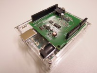
The first prototypes are built and tested and it looks like only some firmware tweaks are needed to finish this project!
Project Elements
150515-schematic.jpg (JPG, 179.49 KB)
150515 PCB v1.0.pdf
(PDF)
Discussion (33 comments)

Peter K Carnegie 3 years ago
Hi
I have been working with Adrian Cole from Australia, (many thanks to Adrian for his patience and detailed feedback), to get the G8JCFSDR working once again with XP, and also to make installing the G8JCFSDR on Linux + Wine systems as straightforward as possible, hence why I'm putting out a request for people to beta test the G8JCFSDR Build 284 release please.
What’s new in Build 284 ?
Windows XP Compatibility
Build 284 restores Windows XP compatibility. I think I inadvertently broke XP compatibility in Build 280 – apologies to all those running Windows XP.
Linux + Wine Compatibility
Build 284 brings the G8JCFSDR to the Linux + Wine environment in a straightforward to install manner, ie as close to the Windows install process/experience as possible.
I only have Ubuntu, Debian and Mint environments, so users with other environments who can test things out would be most welcome.
New Installer Technology
Since its first release, the G8JCFSDR has used InstallShield Express V3.5 SP4 installer technology from back in 2001 !! Express is getting very long in the tooth,
and just does not work properly under Windows 10. Express had worked properly on every OS upto and including Windows 7, but W10 broke it,
(I used a W7 VM under W10 to carry on building the installer packages, but it was getting quite tedious shipping files into the
W7 VM whenever a change was made.
Anyway, I have finally bitten the bullet and summoned up the courage to try something different and upto date, driven by the W10 problem,
and the need for something a lot more flexible to deal with the needs of the Linux + Wine environment,
so I settled on INNO setup (with PERL scripting handling the LINUX specific bits).
I would also like to know that the new installer works properly, and of course that means “guinea pigs” aka field testers please !!
Any problems, suggestions for improvements would be most gratefully received.
The G8JCFSDR Build 284 has been tested under
Mint 19.3 Tricia with Wine 4.0 (32 bit)
Mint 20 Ulyana with Wine 5.0 (64bit)
The setup program may be downloaded from https://www.g8jcf.uk/g8jcfsdr_drt1/downloads/setup_G8JCFSDR_284.exe
On a windows machine just install the G8JCFSDR with a double-click, ie just like you would for any setup.exe.
On a Linux + Wine system, you may find that you need to open up a terminal session
cd ~/Downloads #or wherever you have downloaded the setup program to
then type
wine setup_G8JCFSDR_284.exe
and follow the on-screen instructions. I have attached the Linux + Wine section of the G8JCFSDR User Guide covering installation on Linux + Wine systems, NB the instructions refer to COM1 but the script will in fact use COM16 (I need to update the User Guide) which is a highly unlikely COM port mapping - the majority of Windows programs can only deal with COM1 - COM4, so a 'collision' with an existing wine COM port mapping should be highly unlikely.
The only difference between the Windows install process and the Linux + Wine process is that an additional pre-install step will be displayed before the traditional (for Windows) gui installer kicks in.
Any suggestions for improvements, problems, bug reports, would be most appreciated.
Many Thanks & 73
Peter - GM8JCF
G8JCFSDRUserGuide_284_Linux.pdf (1635kb)
Reply
Show more
1 Attachment(s)
0 Comment(s)

Peter K Carnegie 4 years ago
Hi
The G8JCFSDR Build V 1.0 282 has been released and may be downloaded from http://www.g8jcf.uk/index.htm
Build 282 has many fixes and new features - see the QuickStartGuide for more details.
Higher IF sampling rates
48000 48KHz spectrum display width
96000 96KHz spectrum display width
192000 192KHz spectrum display width
384000 384KHz spectrum display width
assuming that your sound card can support these higher rates – every soundcard I have used supports 48000, and most support 96000, with some supporting 192000, and very few (very expensive) supporting 384000.
Note that the AF output sampling frequency is always 48000 samples/second enabling one to use the inbuilt soundcard and speaker(s) of your system whilst using a higher specification sound card to capture the IF output from the SDR down converter.
Synchronous AM Demodulation
SAM. SAM demodulation can be of help when fading, QSB, causes the AM carrier to almost disappear into the noise. Also, when there is adjacent channel interference. QRM, SAM can be useful to select the opposite sideband to the one being interfered with.
SMD SAM Double Sideband, ie both sidebands used
SMU SAM Upper Sideband
SML SAM Lower Sideband
Additional Calibration Functionality
The SDRShield calibration window in Config has been augmented to provide additional functionality including an improved frequency calibration method.
The IQ Cal Freq facility when switched on generates a carrier 1 KHz up from the current tuned frequency on CLK0 of the SI5351.
If you have a V 2 SDRShield then attach a short length, eg 30cm, of wire to the CLK0 header pins.
If you have a V1 SDRShield then very good soldering skills are required if you want to use this facility, ie not recommended.
The SMeter Cal Freq when switched on generates a 10 KHz square wave on CLK2 of the SI5351 as described in Burkhard Kainka’s book, 7.2, “SDR Hands-on Book”. The output from CLK2 is 3V3 pk-pk or 1.65 V RMS. SMeter levels are measured in micro-volts, uV, so we use an attenuator (see below)), and the fact that square waves are rich in harmonics to generate signals in the uV range at HF. This arrangement will generate an S9 (50uV) signal at 7MHz, S8 at 14MHz, S7 at 28MHz.
Rotary Encoder Tuning, 1602 I2C LCD
Use a rotary encoder for real hardware/knob tuning, and optionally an LCD for frequency display.
Connect a rotary encoder, eg ALPS EC16B2410408 RS 265-1723, A & B to pins 2 & 3 respectively and to OV.
Connect a 1602 I2C LCD, eg https://hobbycomponents.com/displays/74-i2c-serial-lcd-1602-module or of course eBay, to pin A4(SDA) and pin A5(SCL), you will also need to connect Vcc and GND to the I2C LCD module of course.
As always, all feedback would be most welcome
73s
Peter - GM8JCF
soundcardsamplingrate.png (46kb)
samlock.png (8kb)
sdrshieldcalibrate.png (8kb)
sdrshieldrotaryencoder-schem.png (46kb)
sdrshieldrotaryencoder-bb.png (299kb)
smeterattenuator-2-schem.png (26kb)
screenshot-282.png (208kb)
samlock.png (8kb)
sdrshieldcalibrate.png (8kb)
sdrshieldrotaryencoder-schem.png (46kb)
sdrshieldrotaryencoder-bb.png (299kb)
smeterattenuator-2-schem.png (26kb)
screenshot-282.png (208kb)
Reply
Show more
7 Attachment(s)
0 Comment(s)

jmparatte 5 years ago
This shield is very funny. My last check: Read the DCF77 atomic clock. Look to the 1Hz harmonics.
If Elektor plans to redesing the shield - to enhance it - please add 2x 4.7pF to each pins of quartz because the 10pF of Si5351 is not suffisant. The datasheet says 18pF. So my quartz is about 121ppm over!
dcf77-1hz-harmonics.png (218kb)
Reply
Show more
1 Attachment(s)
0 Comment(s)

Peter K Carnegie 5 years ago
Hi
I have generated a beta release of the G8JCFSDR V1.0 Build 281, which may be downloaded from
http://www.g8jcf.uk/g8jcfsdr_drt1/downloads/setup_G8JCFSDR_281.exe
Release Notes for Elektor SDR Shield aka SDR Reloaded V1.0 Build 281
G8JCFSDR V 1.0 Build 281 fully supports the Elektor SDR Shield.
Frequency Calibration V1.0 Build 281
The crystal on the Si5351 is uncalibrated, so you will need to
calibrate the software to allow for the crystal. Go into Config, and click
the Calibrate button on the General tab which will bring up the
calibrate window. Click the Help button to view the procedure you
will need to follow.
G8JCFSDR Build 281 incorporates an improved SDR Shield frequency
calibration algorithm. A new version of the Arduino firmware, V 1.3, is
included with build 281 and should be installed when prompted.
I am very grateful for the perseverance of Jean-Marc Paratte for figuring
out that the original frequency calibration only worked 100% accurately
at 10MHz.
IQ and SMeter Calibration
G8JCFSDR Build 281 uses CLK0 of the SI5351 to generate :-
a) IQ Calibration signal - the IQ calibration signal is generated at +1KHz
from the currently tuned frequency, and if you set the G8JCFSDR to
USB mode you will hear a 1 Khz tone when you switch on the IQ
calibration signal.
b) SMeter 10KHz signal - see Burkhard Kainka's SDR Hands On book,
Chapter 7, section 7.2 pages 79-80 (English Translation) for details of
how the 10KHz signal is used.
These functions are accessed using the Calibrate button on the General
Tab in Config.
Hamlib Support V1.0 Build 281
Build 281 of the G8JCFSDR has a completely different mechanism for using
the Hamlib interface to rigs. This new method has been tested with an
ICOM IC-7200, and supports the following methods with the GM8JCFSDR
1) Set Frequency
2) Set Mode, eg USB, LSB, AM, FM etc
3) Set Bandwidth
When in Hamlib mode, the Notch filtering, Noise Reduction & Noise Blanking
mechanisms of the G8JCFSDR will still function. Build 281 support for
Hamlib is still in very early form and will be improved upon over time.
Firmware Upload
The first time you run the G8JCFSDR and select the Elektor SDR Shield
you will be prompted by the G8JCFSDR to upload the new firmware
to the Arduino Nano.
If you are having problems uploading the firmware, use the StartMenu
entry "XLoader" to manually upload the firmware named "si5351vfoGM8JCF.hex"
usually located in "C:\Program Files (x86)\G8JCFSDR\ArduinoCode". The
StartMenu entry should place you in the correct directory.
Usually I would just place the setup file on the G8JCFSDR website, adjust the
URLs and make Build 281 generally available, but the G8JCFSDR Build 281
includes many changes and extensions which I would like tested before
making it widely available hence why it's classed as a Beta made available
from a direct URL. Feedback will be very gratefully received.
73s
Peter - GM8JCF
Reply
Show more
0 Comment(s)

Peter K Carnegie 5 years ago
Hi
The G8JCFSDR Build 280 is available for download from http://www.g8jcf.uk.
Build 280 is a minor improvement on Build 274, so if you are not experiencing any problems, there is no great benefit from installing build 280.
The need for build 280 has arisen because some users are having problems uploading the .hex firmware into the Arduino Uno which controls the Elektor SDR Shield.
Build 280 includes extra components which should eliminate this problem, specifically :-
1) libusb0.dll is now included into the ArduinoCode directory which should enable averdude.exe to function even when the Arduino IDE isn't installed.
2) The graphical utility XLoader is now installed along with the G8JCFSDR under the G8JCFSDR Start Menu entry so that one can manually upload the .hex firmware to the Arduino Uno.
Some cosmetic changes have also been made to the G8JCFSDR Start Menu entries :-
1) Added Display QuickStartGuide shortcut
2) Added Display Readme shortcut
3) Added Display G8JCFSDR logfile
4) Tidied up G8JCFSDR Trace mode shortcut
5) Added a shortcut to instructions of how to control the G8JCFSDR from the keyboard - I use these to tune the SDR with a Griffin Powermate
6) Added a shortcut to make it very easy to send G8JCF an email using the http://g8jcf.uk website
The G8JCFSDR when currently run in Trace mode, stores the Logfile in 'c:\temp', which is somewhat untidy. Build 280, now uses the user specific environment variable %TEMP% for the directory of where to store the Logfile.
Other changes:-
1) I discovered that Hamlib support has been broken for a long time because of a missing .DLL file, which I have now rectified - does anybody use Hamlib ?
2) The addition of two new receiver interfaces, both of which are unusable by anyone else except myself. If you have a DRT1 and want to use it under Windows with a USB interface, then contact me becauise I do have code for an Arduino Uno which carries out the USB to bit-banging the lines into a DRT1, ie the interface from the PC to the Arduino is a very simple line oriented ASCII protocol, eg f 198000<RETURN>, and the Uno does the work of calculating the DDS register values and then sending them into the DDS chip. In the "good 'ol days" with real serial ports on PCs, this work was all done inside the PC and then bit banged out on the TX, DTR, & DTE lines, but that doesn't work with most USB<->Serial adapters (just too slow).
Finally, Yahoo is shutting down its Yahoo GROUPS service on December 14th 2019, with no more user content allowed to be uploaded after Monday, October 21st, so we will have to migrate to another group site. I have setup a G8JCFSDR group over at GROUPS.IO. Unfortunately to automatically migrate all users and content from Yahoo Groups to Groups.io would cost me USD 220, so G8JCFSDR@GROUPS.IO will start off very sparse, but I would encourage all existing users of G8JCFSDR at Yahoo Groups to sign up for G8JCFSDR@Groups.io please.
73s
Peter - GM8JCF
Reply
Show more
0 Comment(s)

Christian Peret 6 years ago
Bonjour,
Un vieux projet reste dans sa boîte, je viens de refaire une nouvelle tentative.
Suis un gros bleu oui je sais pas besoin de le dire...
Pouvez-vous m'aider un peu a finir ce recepteur
Merci d'avance
Aruino/genuino et la carte elecktor 150515-1 v1.1
C:\Users\on3pcb\Desktop\150515 tuning application installation\si5351vfo3\si5351vfo3.ino:3:29: fatal error: Adafruit_Sensor.h: No such file or directory
#include <Adafruit_Sensor.h>
^
compilation terminated.
exit status 1
Erreur de compilation pour la carte Arduino/Genuino Uno
Reply
Show more
1 Comment(s)

Peter K Carnegie 6 years ago
Hi
G8JCFSDR Website has moved to G8JCF.UK
After many years, Dyndns has decided to end their provision of free internet domains such as G8JCF.DYNDNS.ORG.
In order to carry on making available the G8JCFSDR software, I have registered a new domain, G8JCF.UK which serves out the G8JCFSDR software.
I have paid DYNDNS to have G8JCF.DYNDNS.ORG provided for 12 months so that there should be a smooth transition/migration to G8JCF.UK, ie I hope that search engines will pick up G8JCF.UK so that I can stop paying DYNDNS for G8JCF.DYNDNS.ORG.
URL links which point to G8JCF.DYNDNS.ORG will be automatically redirected, (301 Permanant), to G8JCF.UK for the next 12 months which should update the various search engines so that when G8JCF.DYNDNS.ORG ceases to exist, people will still be able to find the G8JCFSDR software.
The change from FREE to PAY FOR service has served as a salutary lesson to me, ie NOTHING [apart from love :(] in life is really free, and in the end one has to pay for it. It is all too easy to get lured/suckered in by the free offer, and then have to pay later !!
To give you an idea, in my case having to extend G8JCF.DYNDNS.ORG by 1 year (to give search engines time to update), has cost me the same as 10 Years of G8JCF.UK !!
For those interested in how I settled on G8JCF.UK, please read on.
If you need your own domain name, eg G8JCF.UK, I have found that .UK TLDs from WHOIS.COM are very good value for money, about GBP 53/USD 70 for 10 years; then use DYNU.COM for name servers (free) - WHOIS.COM do NOT have a dynamic DNS API which means that for those of us without a STATIC IP keeping the DNS entry synced is not practical, whereas DYNU.COM has a well established dynamic DNS API.
I have no connection whatsoever with either of these organisations, but £5/$7 per year to own your own domain strikes me as great value for money.
I hope this information is useful.
If anybody has problems with the new domain name, and/or the redirect from g8jcf.dyndns.org, please email me at G8JCFSDR (at) GMAIL (dot) COM.
Peter - GM8JCF
Reply
Show more
0 Comment(s)

Peter K Carnegie 6 years ago
Hi
Sometimes, (and I have no idea why), the G8JCFSDR has problems uploading the required Arduino firmware to the Elektor SDR Shield.
UPDATE 2018-11-06 : the cause is if you have NOT installed the Arduino IDE. The G8JCFSDR.EXE upload uses AVERDUDE which is installed with the Arduino IDE. So if you don't want to use XLoader, then just install the Arduino IDE even if you don't intend to use it.
If you are experiencing this issue then you can manually upload the Arduino firmware using the procedure below.
1) Make sure that G8JCFSDR is NOT running
2) Make sure that no other program has the COM port connecting your PC to the Elektor SDR Shield is runing
3) Install XLOADER from http://www.hobbytronics.co.uk/arduino-xloader
4) Using XLOADER, upload
"C:\Program Files (x86)\G8JCF\G8JCFSDR\ArduinoCode\si5351vfoGM8JCF.hex"
directly to the Elektor SDR Shield.
si5351vfoGM8JCF.hex is the firmware for the Arduino UNO.
5) Start up G8JCFSDR - there should be NO request to upload firmware.
Hopefully this will solve the "upload firmware problem", if it doesn't please ask a question
Peter - GM8JCF
Reply

Peter K Carnegie 6 years ago
Hi Chris
That is really great news :) :) !!! I wonder what was going on ?
INPOUT.DLL should also go into SYSWOW64, but I doubt very much that parallel port control of a DDS would actually work on W10, UAC and all that security stuff. I can't think of the last machine I had that had a parallel port on it, must have been an XP machine back in 2005 maybe.
Anyway, onto the really important matter, a decent aerial. I absoultely recommend the M0AYF loop - very easy,cheap,quick to build on stripboard, or get a WellGood pcb from George Smart and build an even better loop, but more expensive (not a lot) than the M0AYF loop.
Good luck, and let us know how your adventures progress
Peter
Reply

Chris Tebarts 6 years ago
Hi Peter,
Uninstalling and reinstalling did not help.
Just to try, I made a fresh install of W10 on another HD, and your software works fine.
So the manual install wil probably solve the problem!
I had a look at the manual install, but the DLL files are at the right spot, they are in SYSWOW64 (I use 64 bit installation) Do the files mentioned from 6) also have to be in SYSWOW64?
One thing i'm sure of: Have to build myself a decent magnetic loop, so I can receive less noise and more stations!
Thanks for all your help!
Chris
Reply

Peter K Carnegie 6 years ago
Hi Chris
That is progress.
Ah, the hazards of working in multiple programming environments re writeln/write vs println/print :) apologies.
Before we get into fixing the G8JCFSDR.EXE, you can try out the Elektor SDR reloaded module using SDRadio from http://www.sdradio.eu/weaksignals/sdradio/index.html for demodulation, and TerraTerm/PUTTY for frequency control using the command f<sp>nnnnnnn<CRLF> where nnnnn is the desired frequency in Hz, eg f<sp>198000<CRLF> for BBC Radio 4 in the UK.
This error msg usally means that a .OCX/.dll is missing or otherwise inaccessible.
1) Try running the G8JCFSDR.EXE as administrator to eliminate any permission problems.
If 1) doesn't work, then it's probably easier to do a complete uninstall of the G8JCFSDR.EXE from Control Panel | Programs & Features, and then do a fresh install.
If you don't want to do the uninstall/reinstall, then take a look at http://www.g8jcf.uk/g8jcfsdr_drt1/g8jcfsdr_manualinstall.htm for details about checking for the various .DLL/.OCX files manually and making sure the various .OCX/.DLL are redistered.
Hopefully you will get there in the end !
Peter
Reply

Chris Tebarts 6 years ago
Hi Peter,
I got the above sketch working after changing Serial.writeln in Serial.write.
Using Teraterm the arduino echo's back the characters I type.
After uploading the GM8JCF software using X-loader the arduino sends 1.1 after sending a "v"
It sends "1.2" when I load the newest file (above) so that all seems okay.
The software on the PC (settings are as described) crashes as soon as I switch to "on"
with a runtime error (see below)
Any idea what's wrong?
Best Regards,
Chris
runtime error (16kb)
Reply

Peter K Carnegie 6 years ago
Hi Chris
I am really flumoxed !!
By default terminal emulators don't do "Local Echo" so U won't see anything on the screen when U press keys. The GM8JCF software doesn't echo back characters which you type and is case sensitive, so all command chars are lower case, the i/f was never intended to be driven by a human hence why it's so simple. It will only send back data in response to commands, eg
v<enter> where v is lower case v, and <enter> should be configured to send CrLF, will return 1.1<CrLf> to the terminal. To be extra cautious, hit <enter> before you type a command letter so as to clear any buffered characters.
OK, let's update the Hello World sketch to take input and send something back.
If this sketch doesn't work, then we're really bandjaxed :(
Hopefully this sketch will work and we can then move on to more complicated matters !
Please let me know how it goes.
Peter
I am really flumoxed !!
By default terminal emulators don't do "Local Echo" so U won't see anything on the screen when U press keys. The GM8JCF software doesn't echo back characters which you type and is case sensitive, so all command chars are lower case, the i/f was never intended to be driven by a human hence why it's so simple. It will only send back data in response to commands, eg
v<enter> where v is lower case v, and <enter> should be configured to send CrLF, will return 1.1<CrLf> to the terminal. To be extra cautious, hit <enter> before you type a command letter so as to clear any buffered characters.
OK, let's update the Hello World sketch to take input and send something back.
/* Use a variable called byteRead to temporarily store
the data coming from the computer */
byte byteRead;
void setup() {
// Turn the Serial Protocol ON
//Change the Baudrate to 115200 once you get this working
//at 9600
Serial.begin(9600);
Serial.writeln("Hello World, let's go";
}
void loop() {
/* check if data has been sent from the computer: */
if (Serial.available()) {
/* read the most recent byte */
byteRead = Serial.read();
/*ECHO the value that was read, back to the serial port. */
Serial.write("You sent ");
Serial.writeln(byteRead);
}
}
OK, try this sketch out with Teraterm/Putty, and when it all works, change the baudrate to 115200 and check that works as well.If this sketch doesn't work, then we're really bandjaxed :(
Hopefully this sketch will work and we can then move on to more complicated matters !
Please let me know how it goes.
Peter
Reply

Chris Tebarts 6 years ago
Hi Peter,
I was not able to get Putty or Teraterm working like you describe. When I type in a character, there is no reaction in the monitor-window, but when you press enter, the RX-LED of the Arduino flashes, but no reaction back. (as if nothing was send)
The Arduino-IDE monitor seems to send a character, but also nothing back.
I tried another Arduino, also a genue one, it behaves the same.
Can the standard setting of the com port in W10 be the problem?
Thanks again for your help!
Chris
Reply

Peter K Carnegie 6 years ago
Hi Chris
That is encouraging news.
The fact you could successfully download the sketch and then saw the "Hello World" message means that communications between the PC and the Arduino is most probably working correctly.
Having downloaded the si5351vfoGM8JCF.hex, and then
when you reset the Arduino you see the signon message also augurs very well, but why the v<return>, as in <return>=CrLf, does NOT work is disappointing. (The business about the bit period doesn't apply when the COM port is being used as a serial port - the bit period is used to specify the timings for RTS/DTR when those lines are used to implement an I2C bus - not relevant in this instance - but see the OLD 2007 Elektor SDR of how RTS/DTR were used to implement I2C from the PC).
OK let's try something else; in PUTTY/TeraTerm; configure the terminal so that the PC <enter> key generates CrLF and then try the v<enter> command.
If this doesn't work then it's time to update the Hello World sketch to accept characters from the PC and do something, eg send back the hex value - send A, get back 0x41(4 chars), to absolutely confirm that communications are completely working properly.
Please keep us all updated.
Peter
Reply

Chris Tebarts 6 years ago
Hi Peter,
I got the above sketch working.
I checked the settings in the G8JCFSDR s/w, is correct, should be, I used the quick quick start guide...
Just one odd thing: In the program the default setting for the bit period is 0,000005000 sec, in the quick quick start guide it reads 0.000005000 sec. (if you set it that way in the program, it changes to 5000 sec...)
with the baud rate at 115200 the G8JCFSDR s/w gives in return:
Si5351 Clockgen (c) GM8JCF 1.2
this happens after every reset of the arduino, there is no reaction on "v"
The arduino serial monitor gives the same result.
Best Regards,
Chris
Reply

Peter K Carnegie 6 years ago
Hi Chris
The "funny characters" often indicates baud rate mismatch. The si5351vfoGM8JCF communicates at 115,200 bps, so in TT/PUTTY try setting the baudrate to 115,200.
Now if that works, ie the v<return> command functions as expected, then the problem is probably that the G8JCFSDR s/w has not been configured correctely.
Do Config, DDS tab, select Ser.
selectSerial I/F tab, select 3 for COM.
Click Apply, Click OK
If TT/PUTTY does NOT work, then I think it's time for a "Hello World" Arduino sketch to verify your Arduino environment.
In the Arduino IDE, enter the following
If you can't get the simple "Hello World" sketch to work, then I'm afraid there must be something wrong with your Arduino environment.
Hopefully you'll find something very soon :)
73
Peter
.
The "funny characters" often indicates baud rate mismatch. The si5351vfoGM8JCF communicates at 115,200 bps, so in TT/PUTTY try setting the baudrate to 115,200.
Now if that works, ie the v<return> command functions as expected, then the problem is probably that the G8JCFSDR s/w has not been configured correctely.
Do Config, DDS tab, select Ser.
selectSerial I/F tab, select 3 for COM.
Click Apply, Click OK
If TT/PUTTY does NOT work, then I think it's time for a "Hello World" Arduino sketch to verify your Arduino environment.
In the Arduino IDE, enter the following
#define BaudRate 115200
#define SIGNON "Hello World Test Sketch"
#define VER "1"
void setup() {
// put your setup code here, to run once:
//Set serial port baud rate
Serial.begin(BaudRate);
Serial.setTimeout(60000);
//Announce we're alive
Serial.print(SIGNON);
Serial.println(VER);
}
void loop() {
// put your main code here, to run repeatedly:
for(;;){
//Tell the world we're alive still
Serial.println("Hello World");
//Wait for 1 second
delay(1000);
}
}
If this sketch works, then we'll update it to include receiving characters from the PC and echoing them back to fully check out the comms link.If you can't get the simple "Hello World" sketch to work, then I'm afraid there must be something wrong with your Arduino environment.
Hopefully you'll find something very soon :)
73
Peter
.
Reply

Chris Tebarts 6 years ago
Hi Peter,
thanks for all your effort, I tried both terminal programs, and it looks like that they connect, but I am not able to give any commands, and the arduino usual gives some rubbish at the start like @2, on one ccasion I saw something like SI5351.
If I disconnect the arduino, the terminal program reacts, so there was a connection.
I'm going to borrow another arduino from a friend, maybe that will work??
Uploading the file you send me with Xloader, seemed to work, I got the message: 15022 bytes uploaded, a bit more than with the original hex-file.
I'll keep you informed.
Best Regards,
Chris
Reply

Peter K Carnegie 6 years ago
Hi Chris
Sorry to hear that you are having problems.
From the PDF, all looks good.
Make sure no programme has opened COM3.
Start up a terminal emulator, eg Tera Term, PUTTY etc.
Open a SERIAL connection to COM3.
Type the v ?<RETURN>
The screen should display the version number of the firmware, eg 1.1<crlf>
If any of the steps above fail then there is a problem with that COM port/Windows. If this is the case then you will need to find out why the COM port is faulty, but since you can upload sketches from the Arduino IDE problems seem highly unlikely.
si5351vfoGM8JCF.hex is located in C:\Program Files (x86)\G8JCF\G8JCFSDR\ArduinoCode and is 41.2 KB (42,277 bytes) in size. So 14734 bytes uploaded doesn't seem correct at all , I would have expected something in the +40kBytes range since the upload protocol is ASCII AFAIK - I don't know much about the STK500 protocol so maybe it's clever enough to send binary data over the async link. I've included my copy of the .HEX file just in case.
If all of the steps above execute successfully, then the connection from the PC to the Arduino is GOOD.
Please let me know what the response to the v ?<return> command was.
73
Peter
Reply

Chris Tebarts 6 years ago
Hi Peter,
Forgot to mention:
I am using windows 10 enterprise, the driver for Arduino loads okay. When your program connects to the Arduino, only one com-led flashes fast. When X-load is active, both LED's seem to light up continuously, until the upload is finished.
Must have something to with the communication, it seems...
Regards,
Chris
Reply

Chris Tebarts 6 years ago
Hi, my name is Chris and I still have the "upload firmware "problem.
Loading a sketch via the IDE works, so my Uno should be okay.
Uploading the compiled version with X-Loader seems to work, I get in return:14734 bytes uploaded.
The G8JCFSDR programme still wants to update the firmware, but does not succed, see the pdf below.
I am sure no other program connecting to com3 is still running, but it still doesn't work, do you have any idea?
Best Regards,
Chris
Arduino board info (149kb)
Reply
Show more
15 Comment(s)

Antony Watts 7 years ago
The broblem with this design is the high impedance input. Most radio system use a 50ohm impedance input.
To overcome this I have wired a 4k7 resistor frm ANT to GND, and wound a toroid transformer on a FT37-43 core of 20/2 turns. This then presents about a 50 ohm input resistance.
I have no trouble running the SDR using a custom written Si5351 Arduino sketch and the HSSDR software with a 96kHz ADC on my Macbook.
Reply
Show more
0 Comment(s)

Lars Jacobsen 8 years ago
Get this error when i try to compile,
>>Arduino: 1.8.1 (Windows 10), Board: "Arduino/Genuino Uno"
C:\Users\LARSJA~1\AppData\Local\Temp\ccYhPjha.ltrans0.ltrans.o: In function `setfreq':
C:\Users\User Name\Documents\Arduino\libraries\si5351vfo2/si5351vfo2.ino:49: undefined reference to `Adafruit_SI5351::setupMultisynth(unsigned char, si5351PLL_t, unsigned long, unsigned long, unsigned long)'
C:\Users\User Name\Documents\Arduino\libraries\si5351vfo2/si5351vfo2.ino:54: undefined reference to `Adafruit_SI5351::setupRdiv(unsigned char, si5351RDiv_t)'
C:\Users\LARSJA~1\AppData\Local\Temp\ccYhPjha.ltrans0.ltrans.o: In function `__static_initialization_and_destruction_0':
C:\Users\User Name\Documents\Arduino\libraries\si5351vfo2/si5351vfo2.ino:7: undefined reference to `Adafruit_SI5351::Adafruit_SI5351()'
C:\Users\LARSJA~1\AppData\Local\Temp\ccYhPjha.ltrans0.ltrans.o: In function `setup':
C:\Users\User Name\Documents\Arduino\libraries\si5351vfo2/si5351vfo2.ino:16: undefined reference to `Adafruit_SI5351::begin()'
C:\Users\User Name\Documents\Arduino\libraries\si5351vfo2/si5351vfo2.ino:22: undefined reference to `Adafruit_SI5351::enableOutputs(bool)'
C:\Users\User Name\Documents\Arduino\libraries\si5351vfo2/si5351vfo2.ino:23: undefined reference to `Adafruit_SI5351::setupPLL(si5351PLL_t, unsigned char, unsigned long, unsigned long)'
collect2.exe: error: ld returned 1 exit status
Multiple libraries were found for "Adafruit_SI5351.h"
Used: C:\Users\User Name\Documents\Arduino\libraries\si5351vfo3
Not used: C:\Users\ User Name\Documents\Arduino\libraries\si5351vfo2
Not used: C:\Users\User Name\Documents\Arduino\libraries\Adafruit_Si5351_Library
Not used: C:\Users\User Name\Documents\Arduino\libraries\si5351vfo2
Not used: C:\Users\User Name\Documents\Arduino\libraries\Adafruit_Si5351_Library
Not used: C:\Users\User Name\Documents\Arduino\libraries\si5351vfo2
Not used: C:\Users\User Name\Documents\Arduino\libraries\Adafruit_Si5351_Library
Not used: C:\Users\User Name\Documents\Arduino\libraries\si5351vfo2
Not used: C:\Users\User Name\Documents\Arduino\libraries\Adafruit_Si5351_Library
exit status 1
Error compiling for board Arduino/Genuino Uno.
This report would have more information with
"Show verbose output during compilation"
option enabled in File -> Preferences.<<
I have follow the guide Peter K Carnegie wrote but it not work
Reply

DF5CL 6 years ago
HI Lars,
About the LCD outout with the blocks: On my display it was necessary to adjust the LCD contrast to makle output visible.
It is not the big pot of the Experimenting Shield, but the small one on the edge.
Further version 2.0 of the Experimenting Shield just has 2 x 8 and not 2 x 16 characters.
The following code did the trick:
//init LCD
lcd.begin(8, 2);
Good DX,
-Peter
Reply

Lars Jacobsen 8 years ago
Hi Peter
I have attached pictures of my configuration, and log files
73
Lars
I have attached pictures of my configuration, and log files
73
Lars
logfiles and pictures (369kb)
Reply

Peter K Carnegie 8 years ago
Hi Lars
The answer has been staring me in the face all the time !!
We need to tell the G8JCFSDR which interface method to use.
So in Config, click on Tab DDS, and then click on the SER radio button in the "DDS I/F Control" area, then configure the rest of the settings, ie Com port, and Elektor SDR Shield.
The G8JCFSDR can interface to SDR hardware using a variety of methods and the default is Parallel - which was the standard/simplest method of connecting external hardware to a PC back in 2004 when the G8JCFSDR was written.
Sorry it's taken me so long to remember the answer - I feel a bit foolish for not realising sooner, still it did mean that I put in some useful stuff into the code.
Very hopefully this will see you on your way.
73
Peter - GM8JCF
Reply

Peter K Carnegie 8 years ago
Hi Lars
Please find attached Build 278. Please unzip etc like you did before.
Build 278 contains more logging and more exception handling.
Also whilst I was going through the code, I found some "peculiar" coding which I can't for the life of me now remember why I coded things that way, way back then (12 years ago). Anyway, with the benefit of hindsight, I "straightened" out that code and whilst it made no difference to my setup, it just might make a difference in your setup. Since the code in question was all about the serial interface and object instantiations, I hope and think the fix I applied might just work (wishful thinking perhaps :o) ! ).
Anyway, could you please give Build 278 a try out.
Very many thanks
73
Peter
Reply

Peter K Carnegie 8 years ago
Hi Lars
Attached are a couple of photos of how I connect the Antenna to the SDR Shield.
I use a bulkhead BNC for the connection to the antenna itself, ie the dupont twisted pair are soldered to the bulkhead BNC.
Hope these are useful
Peter
Attached are a couple of photos of how I connect the Antenna to the SDR Shield.
I use a bulkhead BNC for the connection to the antenna itself, ie the dupont twisted pair are soldered to the bulkhead BNC.
Hope these are useful
Peter
Antenna Connection at GM8JCF (429kb)
Closeup (66kb)
Closeup (60kb)
Top View (97kb)
Closeup (66kb)
Closeup (60kb)
Top View (97kb)
Reply

Peter K Carnegie 8 years ago
Hi Lars
Thank you for the detailed reporting.
I'll have to do some thinking (to say the least), and will probably need to put in some more instrumentation/logging; I'll send you a new version soon
Once again, many thanks for your help, understanding and patience.
73
Peter
Thank you for the detailed reporting.
I'll have to do some thinking (to say the least), and will probably need to put in some more instrumentation/logging; I'll send you a new version soon
Once again, many thanks for your help, understanding and patience.
73
Peter
Reply

Lars Jacobsen 8 years ago
Hi Peter
Here is the log and some pictures of error message from the program.
73 Lars
Here is the log and some pictures of error message from the program.
73 Lars
G8JCFSDR log and error (334kb)
Reply

Peter K Carnegie 8 years ago
Hi Lars
I think the problem is that the OCX file C:\Windows\SysWOW64\MSCOMM32.OCX is not registered to the operating system.
So, could you please carry out the following procedure.
1) Start up CMD.EXE with Run As ADMINISTRATOR
2) At the command prompt do CD C:\Windows\SysWOW64
3) At the command prompt do regsvr32.exe MSCOMM32.OCX
4) A window should pop up saying " .... Succeeded"
I've attached Build 277 which focuses in on the clsElektorSDRShield.GetVer() function call which was the last thing reported in the log file. So could you unzip and copy the new executable into C:\Program Files (x86)\G8JCF\G8JCFSDR folowing the instructions you used for Build 276, eg rename G8JCFSDR_277.EXE to G8JCFSDR.EXE etc.
Now start up Build 277 using the "G8JCFSDR Trace" Start Menu entry and repeat what you did for Build 276
If the registration was the problem then the G8JCFSDR should work correctly. If the registration was NOT the problem, then we should get details in the log file of precisely where the error happened, and if so could U please send me the log file.
Thank you - we must be getting close !!
73
Peter - GM8JCF
Reply

Peter K Carnegie 8 years ago
Hi Lars
I have attached G8JCFSDR_275.ZIP to this posting. The G8JCFSDR Build 276 has been updated with extensive instrumentation/logging in areas concerned with the Elektor SDR Shield.
To use Build 276, please proceed as follows.
1) Rename the existing G8JCFSDR.EXE to something else, eg G8JCFSDR_274.EXE. The G8JCFSDR.EXE is located in C:\Program Files (x86)\G8JCF\G8JCFSDR
2) Download and unzip the attached G8JCFSDR_276.ZIP into C:\Program Files (x86)\G8JCF\G8JCFSDR.
3) Rename C:\Program Files (x86)\G8JCF\G8JCFSDR\G8JCFSDR_276.EXE to C:\Program Files (x86)\G8JCF\G8JCFSDR\G8JCFSDR.EXE
4) Make sure there is a directory named C:\Temp present
5) From the start menu, click on "G8JCF | G8JCFSDR | G8JCFSDR Trace" which will start the G8JCFSDR in logging mode. The G8JCFSDR logging window will be displayed.
6) Now go into Config, and run through the procedure required to configure the G8JCFSDR for the Elektor SDR Shield.
7) At some point the 438 runtime error will be thrown up and the G8JCFSDR will crash out.
8) Now from the start menu, click on "G8JCF | G8JCFSDR | G8jcfsdr Logfile" which will load the log file produced from the last run into Notepad so that you can have a look at what went on.
9) The G8JCFSDR logfile is located at "C:\Temp\G8JCFSDR.log". Please email me that log file so that I can see where the G8JCFSDR failed.
Hopefully with that information I can determine what the problem is and provide a fix.
Thank you for your patience.
73
Peter - GM8JCF
Reply

Peter K Carnegie 8 years ago
Hi Lars
Thanks for the info.
I'm adding extensive instrumentation/logging to the Elektor SDR Shield part of the code which I will send to you, so that we can (try and) find out more precisely where "Run-tme error '438';" is occuring. Unfortunately this will take me a few days, maybe even a week.
Hopefully I will have something to send you to try out in a few days time.
73
Peter - GM8JCF
Reply

Peter K Carnegie 8 years ago
Hi Lars
Hmm :(
OK, I'll have to do some thinking and examining of code to see what/how this problem occurs/can be overcome.
Apologies for the problem.
Can U please check that U have MSComm32.ocx located in your c:\windows\syswow64 directory - this is the OCX which the G8JCFSDR uses to manipulate the COM ports ?
Right, debugging hat on !
73
Peter - GM8JCF
Reply

Peter K Carnegie 8 years ago
Hi Lars
Understand, so it's something specific to the Elektor SDR Shield part of the S/W.
Ah, I think I know what it is - my instructions were incorrect - apologies.
Step 4 should be
4) Click on "Serial I/F" tab, and select the appropriate Com Port; only port numbers 1~10 are valid (I must release a new version which only shows 1-10 !!). Click Apply, Click OK to exit config. Then re-enter Config by clicking the Config button and continue onto step 5.
I think the error is because when you did Step 5, although Step 4 selected the COM port, that selection wasn't actually active, which is why I amended Step 4 to include the Apply, OK part.
Please give it a go and let us know what happens (hopefully success !)
73
Peter
Reply

Peter K Carnegie 8 years ago
Hi Lars
That's bad news :(
My system is 64 bit Windows so the error message is not due to 64 bit windows.
If you select another SDR model, and then do "Power On" you don't get Error 438, is that correct ? ie we need to determine if this error is specific to Elektor SDR shield, or widespread across all SDR models.
Which version of Windows are you running please. The G8JCFSDR works on all windows versions from XP to 10, but Windows 10 might require the "Run As Administrator" setting depending on whether UAC is configured on.
73
Peter
Reply

Lars Jacobsen 8 years ago
Hi Peter
When i reach no. 5 the program crashing, and I get this
Run-tme error '438';
Object doesn't support this property or menthod, I have to select one of the other Elektor and push run and then select Elektor SDR Shield, maybe its can be my system there are course to the probems i using 64 bit system.
When i reach no. 5 the program crashing, and I get this
Run-tme error '438';
Object doesn't support this property or menthod, I have to select one of the other Elektor and push run and then select Elektor SDR Shield, maybe its can be my system there are course to the probems i using 64 bit system.
Reply

Peter K Carnegie 8 years ago
Hi Lars
You are correct, the G8JCFSDR Setup Guide does not cover the Elektor SDR Shield - I must update it :)
To use the G8JCFSDR with the Elektor SDR shield please proceed as follows.
1) Make sure that no program is connected to the virtual Serial Port of your Arduino, eg Arduino IDE, this is VERY important.
2) Install and Startup the G8JCFSDR, but do NOT click the "Power On" button
3) Click on the Config button - if it's not visible, Click "Display Full" - and the Configuration window will be displayed.
4) Click on "Serial I/F" tab, and select the appropriate Com Port; only port numbers 1~10 are valid (I must release a new version which only shows 1-10 !!)
5) Click on "General" tab, and select "Elektor SDR Shield" from the "SDRModel" drop down combo
6) Click on "Soundcard" tab, and select the appropriate soundcard input for the I/Q input from the SDR Shield, and output for the loudspeakers.
7) Click Apply, OK, to exit configuration.
8) Click "Power On" to start receiving.
9) The G8JCFSDR will display a window saying that the Arduino fiormware needs to be updated.
10) Follow the onscreen instructions, and the G8JCFSDR will automatically upload the correct firmware to the Arduino.
11) Once the uploadhas been completed, the G8JCFSDR will start receiving.
Once you are happy that the G8JCFSDR is properly controlling the SDR Shield, you will probably want to perform a Calibration. In which case look further down this forum for a full set of instructions, or just click Calibrate on the General tab in configuration and click the Help button.
Hopefully these instructions will help get you up and running.
Please let us know how it goes
73
Peter
Reply

Peter K Carnegie 8 years ago
Hi Lars
Sorry, No. I use the Elektor SDR Shield with my G8JCFSDR software, so I have no need of an LCD attached to the UNO. The G8JCFSDR directly controls the tuning of the SDR shield to 1Hz precision without any glitching.
Why are U using an LCD since you will also need a PC/MAC/LINUX to demodulate the I/Q output or are U building a h/w phasing/Weaver type receiver ?
73
Peter - GM8JCF
Reply

Lars Jacobsen 8 years ago
Hi,
No I can compile and upload, I have two last questions, the antenna connections what have people do there ?
and the last question, I have an INO file called si5351vfo4 where its possible to get information in LCD display but I only gets dark blocks
73 - Lars OZ4LEJ
No I can compile and upload, I have two last questions, the antenna connections what have people do there ?
and the last question, I have an INO file called si5351vfo4 where its possible to get information in LCD display but I only gets dark blocks
73 - Lars OZ4LEJ
Reply

Peter K Carnegie 8 years ago
Hi Lars
I think you may have installed si5351vfo2 and si5351vfo3 into the wrong location. The directory "C:\Users\User Name\Documents\Arduino\libraries" should NOT contain si5351vfo2 or si5351vfo3. The directory "C:\Users\User Name\Documents\Arduino\libraries" should only contain library code, eg Adafruit_Si5351_Library.
So move/delete the si5351vfo2 and si5351vfo3 directories from inside "C:\Users\User Name\Documents\Arduino\libraries".
Put the si5351vfo2.ino somewhere else, eg "c:\Users\User Name\Documents\Arduino\si5351vfo2\si5351vfo2.ino" and then startup the Arduino ide and load si5351vfo2.ino from the new location.
You might need to comment out the line //#include <Adafruit_Sensor.h>
This is the configuration I have, and I can compile si5351vfo2.ino cleanly.
Let us know how it goes please.
73
Peter - GM8JCF
Reply
Show more
28 Comment(s)

Per Kristenson 8 years ago
Hallo
I got lots of erros when I am running si5351vfo2.
"ccdsteIY.ltrans0.o:(.text+0x440): undefined reference to `Adafruit_SI5351::setupMultisynth(unsigned char, si5351PLL_t, unsigned long, unsigned long, unsigned long)'
ccdsteIY.ltrans0.o:(.text+0x47e): undefined reference to `Adafruit_SI5351::setupRdiv(unsigned char, si5351RDiv_t)'
C:\Users\User\AppData\Local\Temp\ccdsteIY.ltrans0.ltrans.o: In function `global constructors keyed to 65535_0_si5351vfo2.ino.cpp.o.2154':"
I wonder, what is wrong ?
Greetings
Per Kristenson
Reply

Per Kristenson 8 years ago
Hallo Peter
Now it works.
But, I don't know if I did it the right way. I removed all files in the in the si5351vfo2 map, except of hte si5351vfo2.ino file.
I found the Adafruit_SI5351 library in my arduino program, that you mentioned in the earlier mail.
Greetings
Per Kristenson
Now it works.
But, I don't know if I did it the right way. I removed all files in the in the si5351vfo2 map, except of hte si5351vfo2.ino file.
I found the Adafruit_SI5351 library in my arduino program, that you mentioned in the earlier mail.
Greetings
Per Kristenson
Reply

Peter K Carnegie 8 years ago
Hi Per
Have you included the Adafruit_SI5351 library, ie use Sketch | Include Library, and you should see under "Recommended Libraries" the entry "Adafruit Si5351 Library". If the library is not there, then you need to add it; use Sketch | Include Library | Manage Library, then when the window appears, set Type to All, and in the "Filter your Search" box, type in SI5351, which should then show the Adafruit_SI5351 library, click More Info, then click install.
If the library is already installed, then perhaps, the version is incorrect.
Good luck
Peter - GM8JCF
Reply
Show more
3 Comment(s)

kh 8 years ago
I need help to get the SDR working.
Have tried G8Jcfsdr. Running only this prog. Start it , in config serial IF add com6.
It starts, Get msg that firmware must utdates. the Upload window pop up.
in current version show ,
required version 4273 the last may be 8
click on Upload, get error : Fail Arduino Driver SW upload. click on close.
Have tried a few times, same error.
the pc use window 10.
rgds
Kjell
Reply

Peter K Carnegie 8 years ago
Hi Kjell
:(
OK, when you say "Run SDR Arduino shield" which program are you running ?
"run time error 8018" means that another program has control of the COM port and the G8JCFSDR is unable to gain control of the COM port.
To find out if another program has control of the COM port, follow your procedure above, ie "Run SDR Arduino shield" etc, but do NOT startup G8JCFSDR. Instead startup Tera Term and try to make a connection on COM port 6. If as I suspect, another program still has control of COM6, Tera Term will display a "Cannot Open COM6" message window. If Tera Term doesn't complain but connects to the Arduino, verify that all is well by observing the sign-on message. Then in Tera Term do "File | Disconnect". and you should have no trouble when you start up G8JCFSDR.
BTW, COM6 should show up in Control Panel | Device Manager | Ports (COM & LPT) as "USB-SERIAL CH340(COM6)"
If you are running a 32 bit version of Windows, then you can download and install PORTMON from SYSINTERNALS which will show you all kinds of useful information about a port including the process which has it open. If you are running a 64 bit version of Windows, then PORTMON will not work and you must use PROCEXP again from SYSINTERNALS, but it's somewhat more complicated. These and lots of really useful Windows utilities from SYSINTERNALS (now part of Microsoft) are available for download from https://technet.microsoft.com/en-gb/sysinternals/bb545021.aspx
If however Tera Term does give you the error message, then you will have to shutdown/kill programs/processes until you find the one which has COM6 open.
Once again, when the G8JCFSDR is running, you must not have ANY other program which conrols/interfaces to the Arduino running at the same time.
Hopefully we will get to the bottom of this problem very soon !
73
Peter - GM8JCF
Reply

kh 8 years ago
Hi Peter
I have still problem to get the shield working. and get a new error.
I have run into a new error, when I open com6 from your prog
Get run time error 8018.
This is what I do to verify com6 is ok.
Run SDR Arduino shield
select COM6,
open com,
click set
close com
exit
com 6 should not be in use now
Start G8J..
open config
Verify serial is 6
click ok
click ON in power
get run time error 8018
Arduino shield is conect to usb all time
Should I try to uninstal - install to get a fresh instal
Is there a way to get "default setting"?
73 kjell
Reply

Peter K Carnegie 8 years ago
Hi Kjell
Really great news to hear that the G8JCFSDR is working !!
The Quick Starter Guide doesn't include the Elektor SDR Shield. To calibrate the Elektor SDR Shield, go into Config, and click the Calibrate button on the General tab which will bring up the Elektor Shield calibration window. Click Help to view the procedure you will need to follow. I have reproduced the Help text in this posting
To Calibrate the SI5351 Oscilator proceed as follows
Tune in to a strong well known SW AM broadcast station
or better still use an accurate calibrated signal source
such as a signal generator set to 10.000000 MHz
In Europe, there is a time standard station on 9996 KHz
which is usually quite strong, in North America, WWV may be of use
Select LSB demodulation mode - you will probably hear a beat frequency
Ensure that the Low Freq cutoff of the filter is 0
In the Scope source down at the bottom of the main window
Select AF Out, then in the Scope pane select Time
You should see a sinewave albeit with noise.
Click the Config button, Select General tab
Select Elektor SDR Shield, Click the Calibrate button
The Elektor SDR Shield Calibrate window will pop up
The Official Frequency window will show the chosen signal's
frequency as tuned by you
Initially the Actual Frequency window will show the same
Now using the main 7 Segment frequency display, adjust the
receiver frequency until you obtain Zero beat - in the scope
display you should see a longer and longer sinewave as you
approach zero beat - you will also hear the tone go more bassy
flip between LSB and USB several times to very that you have
reached Zero Beat
Now click the Apply button
Set the scope controls back to Frequency, and source to Pre Demod
The main receiver frequency display will change back to the
Official Frequency of the AM broadcast station
but this time the carrier of the broadcast station
should be on 12KHz line and there should be no Beat frequency
If you have achieved Zero Beat, click Done
If you need to try again, Click Reset and repeat the procedure above
If you have an accurate signal source, eg Signal Generator
even better ! Set the generator for 10MHz and carry out the procedure
It's tempting to use MW stations, but I've had limited success
I can get to about 15Hz, but not much better, whereas with a 10MHz
source, a true 0Hz Zero Beat is easily achievable
Once you have applied the Calibration factor, the frequencies used
are stored, and will be used to automatically re-calibrate the SDR shield
each time the G8JCFSDR is started
You can of course repeat the calibration procedure whenever you wish
Hopefully you are now well on your way with the G8JCFSDR and the Elektor SDR Shield. I would be very interested if you have the time, to see what happens if you download the original 1.1 firmware, ie just bring up the calibrate window and click upload. The reason is that I know there are some German, and Dutch users of the G8JCFSDR with the Elektor SDR Shield and I believe that in those locales the , (comma) is the decimal separator just like it is in Norway, and yet they have not experienced the problems which unfortunately beset you. see http://www.elektronik-labor.de/HF/G8JCFSDR.html but of course I fully understand why you might just want to leave well alone now that it's working :)
Take care, and please give us a final report of your success
73
Peter - GM8JCF
Reply

kh 8 years ago
hi Peter.
Beleve this or not.
I thought I should do a config - calibrate, just verify.
I rebooted pc, as the Pc SHUTTED DOWN there was an error message
somthing about memmory,
This is what I did: reboot, when PC was up again I started G8J..
config, calibrate, prtScn , printscreen file named V2-c.gif
Started G8J oce more filename V2-d.gif and V2-e.gif
now it say SW ver 2,
Reply

kh 8 years ago
hi Peter
Have run xloader on _V2.hex and config calebrate , pntScn
kjell
Have run xloader on _V2.hex and config calebrate , pntScn
kjell
v2-a.gif (18kb)
Reply

Peter K Carnegie 8 years ago
Hi Kjell
Interesting, the "Arduino SW Ver" is showing "1," which is what I found when I tried out the LA6XJ version of the firmware on my UK windows. However I would have expected your version/locale of Windows to have caused the G8JCFSDR to correctly convert "1,2" into a floating point number and yet the G8JCFSDR running under a Norwegian Locale shows the version in exactly the same way as my machine running under a UK locale.
So if you upload the regular 1.2 it should show as 1.2 in the Calibrate window just like it does on my machine.
Puzzled !! I'll have to dig around in the source code. In the meantime, here's a different approach to the problem. I've compiled Arduino firmware which reports V as 2, ie no decimal parts so it should convert to floating point without any problems, and since 2 is > 1.1, once downloaded to the Arduino, the G8JCFSDR shouldn't throw up the Update Request.
Sleep well
Peter
Reply

kh 8 years ago
hi Peter
I started with the latesr msg.
Have uploded the La6XJ.zip, copy from terminal
Si5351 Clockgen (c) GM8JCF 1,2
v
1,2
v
1,2
have attach prtsc of calibrete elektor
I started with the latesr msg.
Have uploded the La6XJ.zip, copy from terminal
Si5351 Clockgen (c) GM8JCF 1,2
v
1,2
v
1,2
have attach prtsc of calibrete elektor
nr4.gif (19kb)
Reply

Peter K Carnegie 8 years ago
Also, I have made a special version - attached - of the firmware which reports the version number back as 1,2 which is how I believe decimal numbers are formatted in Norway and much of mainland Europe. Please use XLoader to upload and see if this fixes the problem. If so, then I will have to make changes in the G8JCFSDR code itself to make the version numbering locale neutral.
Thanks
Peter
Thanks
Peter
Reply

Peter K Carnegie 8 years ago
Hi Kjell
The "42738" is an absolute mystery to me, all I can think is that it that it may be due to different locale settings of your PC and mine. The Arduino sends back 1.1 in ascii, which is then converted in the G8JCFSDR to a floating point number, ie 1.1 for English locales.
Your callsign, La6xj, says Norway, so I'm thinking that maybe ascii 1.1 when converted to a floating point number means something else perhaps. If it is that, then I will have to change the source of the G8JCFSDR. I'll do some more tests at my end and see if I can get the 42738 number to give me the clue as to where/why/how it comes from.
Despite having a seeminlgly huge Version number, does the G8JCFSDR work anyway ?
In the meantime, please use XLoader to upload V1.2 firmware to the Arduino, and repeat your tests using Tera Term.
The calibrate button on the General tab should bring up a window as shown in the attachment. The strange colours are because I have my PC screen set to High Contrast black.
Sorry that it's taking so long to get to the bottom of the problems, but we will find out why in the end !
Take care, 73
Peter - GM8JCF
Reply

kh 8 years ago
hi Peter
I have no run Tera Term config: serial port 6, CR send CRLF. Wnen I remove conect USB cabel I get Si5351 Clockgen (c) GM8JCF
When type v I get 1.1
CR no reply
Have not upgraded to 1.2, should I do it now?
When I click on Calibrate, I get this window
The Calibrate Elektor Si5351 Xtal
Official Frequency 010000 hz
Acrual Frequency 010000 h
Arduion SW ver 42738
There is 4 button: Reset, Apply, Cansel, Done
Reply

Peter K Carnegie 8 years ago
Hi Kjell
Your problems got me looking very carefully at the Arduino firmware tonight, and whilst the current version, ie 1.1 works satisfactorily, there are rare conditions when 1.1 doesn't respond as corectly as it should. To that end, I've updated the firmware to V1.2 to include more stringent checks on the communications interface, and have attached the .hex to this post.
Rename C:\Program Files (x86)\G8JCF\G8JCFSDR\ArduinoCode\si5351vfoGM8JCF.hex to C:\Program Files (x86)\G8JCF\G8JCFSDR\ArduinoCode\si5351vfoGM8JCF_1,1.hex so that if things don't work out you can always revert back to the current firmware version
Then Unzip si5351vfoGM8JCF.zip into the C:\Program Files (x86)\G8JCF\G8JCFSDR\ArduinoCode folder.
Startup G8JCFSDR but don't click ON, click config, click General tab, click Calibrate, then on the Calibrate window you should see "Arduino SW Version" 1.2, click the Upload button which will upload the new firmware.
Click Done, then close the Config window, and startup the G8JCFSDR.
Reply

Peter K Carnegie 8 years ago
Hi Kjell
The message windows are a puzzle to me.
OK, we need to do some debugging please !
Make sure G8JCFSDR is closed down completely.
Use XLoader to upload the firmware as described earlier in this thread.
Next start up a terminal emulator program such as Tera Term - see https://osdn.net/projects/ttssh2/releases/ or putty if you haven't got a suitable terminal emulator.
In your terminal emulator open a connection to the Serial port of your Arduino, with a bit rate of 115,200, in your case I believe that's COM6, and set the terminal to send CRLF when you type <return>. It also helps if you set Local Echo on so that you can see what you are typing. The Arduino should respond with "Si5351 Clockgen (c) GM8JCF<crlf>"
Now in the emulator type v
The arduino should respond with "1.1<crlf>"
If the above responses all work, then that proves that the Arduino has the correct firmware loaded and running.
If you don't get these responses then something is wrong with your Arduino, and we'll have to carry out further investigations using the Arduino IDE, but for now I am going to assume that the Arduino firmware is loaded and running successfully.
Now close down the terminal emulator.
Make sure no other program is running which uses the Arduino COM port. This is very important, other programs which try to control the Arduino MUST NOT be loaded/running.
Start up the G8JCFSDR, but do NOT click ON. Go into config, select tab "Serial I/F" and make sure the COM port is set correctly. Exit config
Click ON, the G8JCFSDR should start running without requesting Arduino firmware update.
Hopefully all will be well !!
Let us know how it goes
73
Peter - GM8JCF
Reply

Peter K Carnegie 8 years ago
Hi Kjell
Thanks for the clarification about the message. I'm still puzzled that it said "required version 4273", the required version should be 1.0 or greater.
Anyway re the PrtScn, the resolution will be whatever your screen is, eg 1920x1080 which is not very big at all.
Did you try the Xloader procedure ?
73
Peter - GM8JCF
Reply

kh 8 years ago
Thanks for quick reply. I think the text/message is easy to misunderstand
"required version 4273" This is msg from update screen. Then I could not read last number/diget, so I wanted to tell the last may be 8". Sorry for that. English is not that easy.
I have done a few PrtScn as jgp files, What reselution should I use?
73
Kjell la6xj
"required version 4273" This is msg from update screen. Then I could not read last number/diget, so I wanted to tell the last may be 8". Sorry for that. English is not that easy.
I have done a few PrtScn as jgp files, What reselution should I use?
73
Kjell la6xj
Reply

Peter K Carnegie 8 years ago
Hi Kjell
That's a very strange message, "required version 4273 the last may be 8", I'm hard pressed to understand how that message has appeared, that text is not in the source code of the G8JCFSDR. Can U screenshot the window and post it here please ?
Also, there is another way of downloading the firmware to the Arduino without having to load up the Arduino IDE etc. Please proceed as follows.
0) Goto http://www.hobbytronics.co.uk/arduino-xloader download and install arduino-xloader.
1) Close G8JCFSDR if it is running
2) Run xloader;
4) Now start up the G8JCFSDR, you should NOT be prompted to upload firmware.
Please give this a try and let us know how it worked out.
Good luck, 73
Peter - GM8JCF
That's a very strange message, "required version 4273 the last may be 8", I'm hard pressed to understand how that message has appeared, that text is not in the source code of the G8JCFSDR. Can U screenshot the window and post it here please ?
Also, there is another way of downloading the firmware to the Arduino without having to load up the Arduino IDE etc. Please proceed as follows.
0) Goto http://www.hobbytronics.co.uk/arduino-xloader download and install arduino-xloader.
1) Close G8JCFSDR if it is running
2) Run xloader;
- Set baudrate to 115200
- Set COM port accordingly - looks like COM6 in your case
- Set the device to UNO
- Use the browse button to navigate to wherever you installed the G8JCFSDR and then into the ArduinoCode directory under there, eg C:\Program Files (x86)\G8JCF\G8JCFSDR\ArduinoCode, then select si5351vfoGM8JCF.hex
- Click upload. Xloader will then upload the .hex file to the UNO.
4) Now start up the G8JCFSDR, you should NOT be prompted to upload firmware.
Please give this a try and let us know how it worked out.
Good luck, 73
Peter - GM8JCF
Reply
Show more
23 Comment(s)

robin_h_p 8 years ago
I have a problem updating the Arduino firmware. The Arduino is connected to COM7 and the Elektor programme is running, but the update goes to COM1 and after ten tries gives up.
What am I doing wrong?
Reply

Peter K Carnegie 8 years ago
Great news Robin.
I can't tell you how much the M0AYF loop was/is responsible for keeping me listening to shortwave when all the noise has been building up especially on 160/80 and 40m !
Search the Internet for "M0AYF Wideband Loop" and you will come across lots of comments/reviews/projects.
Take care, 73
Peter
I can't tell you how much the M0AYF loop was/is responsible for keeping me listening to shortwave when all the noise has been building up especially on 160/80 and 40m !
Search the Internet for "M0AYF Wideband Loop" and you will come across lots of comments/reviews/projects.
Take care, 73
Peter
Reply

robin_h_p 8 years ago
Hi Peter,
Thanks for the info on the COM port, I get it.
Also many many thanks for the extensive antenna suggestion, it sounds good and will be my next step.
It turns out I missed a connection on the antenna shield (circuits shown in Elektor 11-12 2016), which I fitted on top of the SDR shield. Didn't check it properly and thus the bad result.
I have also built an extension to get away from the noise sources you mentioned, which allows me to fit a telescopic antenne or a magnetic loop antenna (later) located by a window. The circuit is in a neat aluminium case I had and is fitted with jumpers for choice of antenna circuit.
73's
Robin
Reply

Peter K Carnegie 8 years ago
Hi Robin
The reason you can't run the G8JCFSDR at same time as running the Elektor tuning program is that only one program at a time is allowed to control a COM port. in Windows and most operating systems
The G8JCFSDR directly interfaces to the Elektor SDR Shield to control the frequency and hences has to open and control the COM port.
HDSDR, SDR# don't control the Elektor SDR Shield's frequency, and hence those programs don't ever open the COM port, so no conflict ! (which is of course why you need to run the Elektor tuning program)
Regarding a reasonable Antenna setup, for General Coverage I have built and use an M0AYF active loop - a poor man's Wellbrook if you like !!! see http://www.qsl.net/m0ayf/active-loop-receiving-antenna.html
I find the M0AYF loop works very well from 77,5 KHz and is usable up to broadcast FM stations, although it works best in the 100KHz ~ 30MHz range.
The really great thing is the loop seems to cut out all the local interference from TVs, computers, SMPSU, LED lighting, VDSL etc, ie all the digital stuff which is so convenient to use, but which creates such noise smog on the HF bands. Before I built the loop I could only pick up strong signals because the noise levels were so high.
It's also really quick, cheap and simple to build.
73
Peter - GM8JCF
Reply

robin_h_p 8 years ago
Yes thanks, it has solved that problem. I should have seen this in your manual.
As It turns out, one must not run the Elektor (Pre-selector) programme with G8JCFSDR. If you do it blocks the COM port and G8JCFSDR will not run.
With SDR# or HDSDR this is not a problem, in fact it says you should run it in the Elektor articles.
I am still working on an improvement to the aerial, as reception is very very poor.
Thanks again,
Robin
Reply
Show more
8 Comment(s)

Peter K Carnegie 8 years ago
I have always been keen to ensure that the G8JCFSDR fully supports the various Elektor SDR initiatives, and the new Elektor SDR Shield is no exception, and given the strap-line, “SDR Reloaded”, it is only fitting that the G8JCFSDR should also be “Reloaded” !
So, I am very happy to let you know that the G8JCFSDR, Build 274, fully supports the Elektor SDR Shield.
The Elektor SDR Shield support on the G8JCFSDR provides
The G8JCFSDR is available for download from http://www.g8jcf.dyndns.org
Also please see Burkhard's page at http://www.elektronik-labor.de/HF/G8JCFSDR.html
Peter - GM8JCF (I moved to Scotland since the last Elektor SDR)
So, I am very happy to let you know that the G8JCFSDR, Build 274, fully supports the Elektor SDR Shield.
The Elektor SDR Shield support on the G8JCFSDR provides
- 1Hz tuning precision with NO glitching
- Easy to use calibration facility to ensure that your SDR Shield is always spot-on frequency
- Built-in Arduino firmware upload facility to make upgrading really simple
The G8JCFSDR is available for download from http://www.g8jcf.dyndns.org
Also please see Burkhard's page at http://www.elektronik-labor.de/HF/G8JCFSDR.html
Peter - GM8JCF (I moved to Scotland since the last Elektor SDR)
Reply

Peter K Carnegie 8 years ago
Hi Remis
Good news. The VFO1 and VFO2 sketches as far as I can remember do not support 1Hz precision tuning, and their protocol is very different from the GM8JCFVFO protocol.
I could write a LINUX based VFO controller if there is sufficient interest, but not the DSP part - I assume that you have that already covered - if so, pls try using a terminal emulator to control the Arduino frequency, and your DSP software for demodulation.
73
Peter - GM8JCF
Reply

remis 8 years ago
Hello Peter. I confirm it works with space and si5351vfoGM8JCF.hex file
at 115200 bauds. summary command:
f<sp>198000<crlf>
c<sp>?<crlf>
f<sp>?<crlf>
v<crlf>
(just for remember the initial vfo2 and vfo1 sketch in 150515-11 SDR software complete.zip (752.9 KB) works at 9600 bauds and doesnt have the same behaviour)
73*73
remis
at 115200 bauds. summary command:
f<sp>198000<crlf>
c<sp>?<crlf>
f<sp>?<crlf>
v<crlf>
(just for remember the initial vfo2 and vfo1 sketch in 150515-11 SDR software complete.zip (752.9 KB) works at 9600 bauds and doesnt have the same behaviour)
73*73
remis
Reply

Peter K Carnegie 8 years ago
Hi Remi
The commands are always a letter then space then a value, eg
f<sp>198000<crlf>
c<sp>?<crlf>
and so on
The only exception is version which is simply
v<crlf>
where SPACE = <sp> = \x20 for C/PERL etc programmers
Give that a go and let us know please
73
Peter - GM8JCF
The commands are always a letter then space then a value, eg
f<sp>198000<crlf>
c<sp>?<crlf>
and so on
The only exception is version which is simply
v<crlf>
where SPACE = <sp> = \x20 for C/PERL etc programmers
Give that a go and let us know please
73
Peter - GM8JCF
Reply

remis 8 years ago
Hello Peter. Thanks for this detailed answer. I try the hex file si5351vfoGM8JCF.zip (16.13 KB) with xloader.
After restart I see in terminal :
Si5351 Clockgen (c) GM8JCF 1.2
with "v" , answer is "1.2"
"c?" and other commands have no effect. I suspect that I'm not using the good version. (I only have the *.ino file from VFO2 and VFO3 for home compilation)
73
Remi
After restart I see in terminal :
Si5351 Clockgen (c) GM8JCF 1.2
with "v" , answer is "1.2"
"c?" and other commands have no effect. I suspect that I'm not using the good version. (I only have the *.ino file from VFO2 and VFO3 for home compilation)
73
Remi
Reply

Peter K Carnegie 8 years ago
hi remis
The si5351vfoGM8JCF.hex Arduino firmware communicates over a virtual com port using a very simple protocol and so it should be very easy for someone who knows how to program a GUI under Linux, eg Gambas, C# Mono, to do VFO adjustment.
The si5351vfoGM8JCF.hex protocol is as follows :
All command leters are lower case, each line sent to the Arduino is terminated with CRLF, responses from the Arduino are terminated with CRLF, the Arduino firmware does not echo back characters sent to it, frequencies are always in Hz, and leading zeroes are not required.
1) 115200 BPS
2) 8 data 1 stop no parity, no flow control
3) f nnnnnnn<crlf> to set the frequency where nnnn is the frequency in Hz
leading zeroes are not required, eg f 198000 will set the receive frequency to
198KHz for BBC R4 LW, eg 5505000 will set the receive frequency to 5.505MHz
for Shannon Volmet.
4) f ?<crlf> returns the current tuned frequency
5) c ttttt aaaaa<crlf> to set the correction factor for the SI5351 XTAL,
eg c 10000000 9999800, ie the official frequency is 10MHz, but we have
to tune the SI5351 to 9.999800 MHz to zero beat with 10MHz
6) c ?<crlf> returns the current calibration factor
7) v<crlf> returns firmware version, eg 1.1
You can try these all out from a terminal emulator on your Linux box.
Hope this helps get a Linux VFO controller written.
73
Peter - GM8JCF
Reply
Show more
6 Comment(s)

Peter Marx 8 years ago
I'd like to build the magnetloop antenna from Elektor 10/2016 for the SDR shield.
The circuit diagram contains a 10u cap. What type can i use here ? There seem to be no ceramic caps with 10u, but only very bulky, expensive types.
Or can I use a Tantal type here ?
The circuit diagram contains a 10u cap. What type can i use here ? There seem to be no ceramic caps with 10u, but only very bulky, expensive types.
Or can I use a Tantal type here ?
Reply

Peter K Carnegie 8 years ago
On eBay search for "monolithic ceramic capacitor 10uF" and you should find some eg http://www.ebay.co.uk/itm/Multilayer-Chip-Monolithic-Ceramic-Capacitor-Multi-listing-/221244997710?var=&hash=item33833ac04e:m:mIlcHFWtyj7HcXUiknYYA-g
Reply
Show more
2 Comment(s)

NECV20 8 years ago
In a comment to this project Ralf Kaucher – DK9PS – asked if it is possible to have a extio.dll to command the ElektorSDR directly by the HDSDR program.
In response Burkhard Kainka asked if someone was willing to assist in programming in C to get the job done.
But there is another way to get HDSDR to command the SDR receiver by using OmniRig. With OmniRig the way the two-way communication is described in a .ini file which can be made and edited by a simple wordprocessor.
In a nutshell here is what you do:
1) Learn about OmniRig by visiting www.dxatlas.com/OmniRig
2) Download OmniRig and the INI files from www.dxatlas/Download.asp (it is freeware)
3) Unzip the packages and install by running OmniRigSetup.exe
4) Add your ini file for ElektorSDR to the folder “Rigs” (my ElektorSDR.ini is in the attachments), which in my case can be found in c:>ProgramFiles(x86)>Afreet>Omnirig (and yes mister Bill Gates, I really want to to that)
5) Start HDSDR select Options [F7] “Cat to Radio (Omni-Rig)” and make the setup and select the necessary sync's
6) Load a new sketch (si5351vfo2-or or si5351vfo3-or – see the attachment) in the arduino which can cope with the OmniRig commands and requests
Or read more about it in the elaborate setup instruction which is in the attachments of this comment (instruction text, ElektorSDR.ini file, sketches).
Reply
Show more
1 Attachment(s)
2 Comment(s)

phase2682 8 years ago
I was able to compile Si5353 vfo2 and Si5351 vfo3 successfully and uploaded to the uno before mounting the SDR shield. On the serial monitor I received the 'Si5351 Clockgen' or 'Si5351 VFO' message followed by 'OK' as expected. But after mounting the SDR shield to the uno I get the 'Si5351 Clockgen' or 'Si5351 VFO' message but nothing else: no 'OK' or 'Errors'. it appears that the Si5351 is not able to setup. I verified that there is +5V and 3.3V on the shield.
if I hook an antenna to the shield and connect to a sound card I receive a strong local AM broadcast station thru SDR#. I can tell that the shield is not responding to any input to change frequency.
I reloaded the Adafruit_Si5351 library with no change. Any ideas on what is wrong?
if I hook an antenna to the shield and connect to a sound card I receive a strong local AM broadcast station thru SDR#. I can tell that the shield is not responding to any input to change frequency.
I reloaded the Adafruit_Si5351 library with no change. Any ideas on what is wrong?
Reply
Show more
1 Comment(s)

maxhusky 8 years ago
The two boards would make a real fine portable (for outdoor use with less home made noise!) receiver if no PC is necessary. No waterfall display nor a band scope, just AM, SSB and a few filter bandwidths. Maybe this can be done with a low power Cortex M4.
Peter
Peter
Reply

Peter K Carnegie 6 years ago
Hi Peter
I've given some more thought to the idea of a truly portable SDR setup, and I think the quickest/simplest way might be to use a low cost Windows 10 tablet, eg https://www.ebuyer.com/840806-linx-820-tablet-pc-820-1802a232b03, GBP 117.66 inc. vat and then connect up the SDR H/W front-end. This way, you get the full PC style SDR functionality, eg high resolution spectrum display, and of course you can use almost any SDR front-end. Armed with several power banks, one should be able to stay 'off-grid' for days at a time, and of course if you have a car, the power banks/tablet can be charged from the cigar slighter socket. The G8JCFSDR was developed originally on a 333MHz Celeron laptop (which is why I had to use assembler for the dsp functions), and works just fine on intel atom notebooks, so I'm quite confident it will work on the low cost tablets.
I think I might get one of these Win10 tablets and see how it goes :)
73
Peter
Reply

maxhusky 6 years ago
Hi Peter,
thanks for your suggestions.
I already use an indoor magnetic loop and it shows much lower noise compared to my active whip. Nevertheless there is still some "home made" noise with the loop.
Something like the Tecsun or a Degen might be an good idea. The Elad FDM is nice, but in fact a bit costly.
Peter
Reply

Peter K Carnegie 6 years ago
Hi Peter
I understand what you mean about the "electronic smog" .
Before we go to the trouble and expense of producing a true standalone SDR based on the Elektor SDR, may I suggest that you try some of the following ideas.
1) Build an M0AYF active loop antenna. I have one of these and it made all the difference for me. https://www.qsl.net/m0ayf/active-loop-receiving-antenna.html very quick, cost effective, simple to build.
2) For better performance build a Wellgood loop, https://www.george-smart.co.uk/projects/wellgood_loop/
3) I have a Tecsun PL600 which I sometimes take with me when I go walking up the local mountain which gives me very good results indeed. A more modern model is the TECSUN PL660. https://authorizedboots.com/2015/11/tecsun-pl-660-review/
4) If you must have an SDR, then take a look at the ELAD, http://ecom.eladit.com/epages/990298944.sf/en_GB/?ObjectPath=/Shops/990298944/Products/%22ELAD%20FDM-DUOr%22 but that is some serious money !!!!
Getting back to a standalone SDR based on the Elektor SDR h/w, it's not the difficulty of the s/w or h/w, but the whole business of making a PCB, amd packaing the lot into a suitable enclosure with the TFT cutout, front panel controls, and rear panel connectors. My prototype runs off a 5V powerbank quite satisfactorily, but as I said previously, my prorotype is built on breadboard and so is quite unsuitable to be moved :).
Anyway, if there is enough interest, and perhaps Elektor themselves might be interested then I will progress the prototype to a proper packaged solution.
Please consider some of the above suggestions, they may suit your circumstances.
73
Peter
Reply

maxhusky 6 years ago
This sounds promising. There are lots of SDR which need a PC or similar. But as there is much man made noise around even in not denesly populated areas I would like to have a robust, portable receiver to listen to rare radio stations somewhere far away from RF noise sources , e.g. on hills/moutains. So, I am very interested.
Peter
Peter
Reply
Show more
5 Comment(s)

phase2682 8 years ago
The laptops I was going to use (latitude e6530) have a combo audio jack for stereo headphone and only a mono microphone input. Any ideas on how to access both channels of the sound card?
Reply

Analphabeet 8 years ago
My last comment is not quite right: first I have to mention that I am using an Acer Aspire and second there is no shortcut between L and R: there is no microphone-entrance at all. There is only the build-in mike of the system. I was to Quick to place my comment. Perhaps it works with a Latitude e6530. Please forgive my hurry.
Reply

Analphabeet 8 years ago
Hello Lars and phase 282,
The splitter that you, Lars, show does not work in this case: it provides a stereo-signal on the jack-plug but the jack-bus on those laptops makes a shortcut between L and R. An external soundcard delivers a stereo-signal to the USB-port of your the laptop and the USB-port manages it as a stereo-signal.
Reply

Lars Jacobsen 8 years ago
Analphabeet and phase2682 If both of you have a combo port, You can visit the local computer store and buy a Y-cable like this http://forum.benchmark.rs/attachment.php?attachmentid=131797&d=1388163760 when you have this, go to settings for Microphone and select "Listing to this" :-), I do it my self
Reply
Show more
5 Comment(s)

Klaus Hirschelmann 8 years ago
Hello,
maybe there also is some interest in my version of SDR controller. I am using the "LCD KEY SHIELD" from ElecFreaks, because besides the 16x2 character LCD there also is an increment encoder and joy stick on board.
Firmware version has been made especially for this type of shield. It allows SDR incremental tuning from 0.1 to 30.0 MHz. The joy stick is used for tuning step selection between 100 Hz and 1 MHz.
By pushing the button combined with increment encoder, currently tuned frequency will be stored within internal EEPROM of processor for use as future starting frequency,
Here you can download the firmware sketch and pictures showing the SDR in operation :
http://www.kh-gps.de/Elektor_VFO_V10.zip
Reply

Klaus Hirschelmann 8 years ago
You are right and i have to excuse for NOT removing the line:
#include <Adafruit_Sensor.h>
In my case also without removing this line, compilation did work without any problems, but there was some place, where Burkhard Kainka ( program author of original firmware ) meanwhile did write about this ( text automatically translated by Google ):
Elektor-Labs reported that there were problems with entry
#include <Adafruit_Sensor.h>
What actually has to do with the sensor library, I've also asked myself. After some search, it has become clear. This library was falsely registered in Adafruit_SI5351.h, but was never used. To compile everything I had to use it in my source code. Meanwhile the error was corrected in the current library. And anyone who now uses the new library with my cold source code will get an error message. You must then remove the line #include <Adafruit_Sensor.h> from the source code.
#include <Adafruit_Sensor.h>
In my case also without removing this line, compilation did work without any problems, but there was some place, where Burkhard Kainka ( program author of original firmware ) meanwhile did write about this ( text automatically translated by Google ):
Elektor-Labs reported that there were problems with entry
#include <Adafruit_Sensor.h>
What actually has to do with the sensor library, I've also asked myself. After some search, it has become clear. This library was falsely registered in Adafruit_SI5351.h, but was never used. To compile everything I had to use it in my source code. Meanwhile the error was corrected in the current library. And anyone who now uses the new library with my cold source code will get an error message. You must then remove the line #include <Adafruit_Sensor.h> from the source code.
Reply

ikkeje 8 years ago
Hello,
The sketch si5351vfo3.ino is compiled with a lot of errors when the line :
#include <Adafruit_Sensor.h> Is present
THe first error is:
undefined reference to `Adafruit_SI5351::setupMultisynth(unsigned char, si5351PLL_t, unsigned long, unsigned long, unsigned long)
Everything seems to be OK without this line.
Can you tell me the purpose of tis line, there is no sensor in the SDR
Thanks,
Ikkeje
Reply
Show more
3 Comment(s)

Burkhard Kainka 8 years ago
The main problem was the exact tuning. The 25 MHz clock can be up to 3 kHz higher. I made a new tuning software with calibrated clock and tuning in 20 Hz steps. Now WSPR works.
http://www.elektronik-labor.de/HF/SDRshield.html#wspr
wspr.jpg (129kb)
using the Elektor Extension Shield (1kb)
Reply
Show more
2 Attachment(s)
0 Comment(s)

Per Kristenson 8 years ago
I get this error when I run the SDR program on
my ardiuno?
"C:\Program Files\Arduino\libraries\si5351vfo2\si5351vfo2.ino:3:29: fatal error: Adafruit_Sensor.h: No such file or directory
#include <Adafruit_Sensor.h>"
my ardiuno?
"C:\Program Files\Arduino\libraries\si5351vfo2\si5351vfo2.ino:3:29: fatal error: Adafruit_Sensor.h: No such file or directory
#include <Adafruit_Sensor.h>"
Reply

DF5CL 6 years ago
Please check the version of the etherkit library.
Sir Kainka's Elektor Article links to:
https://github.com/etherkit/Si5351Arduino
But the most recent release has additional parameters, so compilation will most likely fail without amendment.
But if you ceck under "releases", you might find an older release (v.1.2.1) that compiles fine.
https://github.com/etherkit/Si5351Arduino/releases/tag/v1.1.2
Good Luck!
Reply

Lars Jacobsen 8 years ago
Hi,
I have a little problem, every time i try to compile the ino files i get an error like this
Build options changed, rebuilding all
si5351vfo4.cpp.o: In function `setfreq(unsigned long)':
C:\Program Files (x86)\Arduino/si5351vfo4.ino:67: undefined reference to `Adafruit_SI5351::setupMultisynth(unsigned char, si5351PLL_t, unsigned long, unsigned long, unsigned long)'
C:\Program Files (x86)\Arduino/si5351vfo4.ino:72: undefined reference to `Adafruit_SI5351::setupRdiv(unsigned char, si5351RDiv_t)'
si5351vfo4.cpp.o: In function `setup':
C:\Program Files (x86)\Arduino/si5351vfo4.ino:26: undefined reference to `Adafruit_SI5351::begin()'
C:\Program Files (x86)\Arduino/si5351vfo4.ino:32: undefined reference to `Adafruit_SI5351::enableOutputs(bool)'
C:\Program Files (x86)\Arduino/si5351vfo4.ino:33: undefined reference to `Adafruit_SI5351::setupPLL(si5351PLL_t, unsigned char, unsigned long, unsigned long)'
si5351vfo4.cpp.o: In function `__static_initialization_and_destruction_0':
C:\Program Files (x86)\Arduino/si5351vfo4.ino:6: undefined reference to `Adafruit_SI5351::Adafruit_SI5351()'
collect2.exe: error: ld returned 1 exit status
error in compilering.
I get the same error in VFO2, VFO3, VFO4
anybody there can help ?
Reply

Burkhard Kainka 8 years ago
In early versions of Adafruit_SI5351.h the library<Adafruit_Sensor.h> was included but not used. It was removed at last. So if you use the new library, please remove this line from the vfo-software:
#include <Adafruit_Sensor.h>
I attached the new software without the Sensor library plus one more version. si5351vfo4 uses the LCD and the buttons on the Elektor LCD shield for standalone tuning.
#include <Adafruit_Sensor.h>
I attached the new software without the Sensor library plus one more version. si5351vfo4 uses the LCD and the buttons on the Elektor LCD shield for standalone tuning.
vfo2/3/4 (37kb)
Reply
Show more
6 Comment(s)

Burkhard Kainka 8 years ago
Vatentin wrote: But i've got only noise. Even in MV/LW band… Something wrong somewhere :(
The problem is noise from all the electrical equipment in houses. And also many powerful stations were shut down. So there are two things to observe.
1. Try it after sunset. There are more stations and better conditions at night
2. Try to use an outside antenna or a shielded magnetic loop like this one: http://www.elektronik-labor.de/HF/BreitbandAntennen.html#loop2
Reply
Show more
0 Comment(s)

Ralf Kaucher 8 years ago
Works in principle well with the Arduino Shield Tuning program. Tested with some meters of wire, several broadcast stations may be heared. But what is about HDSDR? Is there a matching extio.dll available?
Ralf - DK9PS -
Ralf - DK9PS -
Reply

NECV20 8 years ago
I still have to wait a while for the board to arrive, but I think I go try to use it with fldigi (see www.w1hkj.com). Fldigi will connect by (virtual) serial port to a "rig", and communicating with the radio can be programmed by constructing a mark-up languare like xml file. How to do that is explained in the attachment.
Reply
Show more
2 Comment(s)

Burkhard Kainka 8 years ago
Noise from USB and the computer can find its way into the input, mainly via the ground line. I try to avoid this by using an RF transformer at the Antenna line. Also it is really a hard job to avoid noise from inside the house. Right now I use a wire antenna in the garden plus ground radial and two RF transformers 3 : 1 and 1 : 3 on both sides of the Antenna cable. Buts still there is more noise than normal. Right in the middle of a big city things are difficult.
Reply
Show more
0 Comment(s)

Charles Muller 8 years ago
Do you find that the Arduino or USB connection (with switch mode PS, etc.) causes noise problems for MF/SW reception? A decent antenna would always help, but I am just wondering if noise is a problem?
Regards, and thanks for a great project!
Charles.
Regards, and thanks for a great project!
Charles.
Reply
Show more
0 Comment(s)

Burkhard Kainka 8 years ago
I guess the project will never be completely finished. Software and special applications will follow. There is a new standalone tuning software using the LCD shield. And also many digital modes on shortwave are to be tested.
Standalone tuning the vfo (7kb)
..using the lcd shield (87kb)
Reply
Show more
2 Attachment(s)
0 Comment(s)
Updates from the author
Lucky 8 years ago
c4software 8 years ago
What is the difference between the si5351vfo2 and si5351vfo3 ?
Thanks
DC7FB 6 years ago
Can i use them?
second question: ist there an place to talk in german over this very interesting project?
DF5CL 6 years ago
Schau mal auf: http://www.elektronik-labor.de/HF/SDRshield.html#wspr
Hier findest Du einiges zu diesem Thema in deutscher Sprache.
vy 73
DF5CL
Lucky 9 years ago
Burkhard Kainka 9 years ago
http://www.elektronik-labor.de/Arduino/VFO.html
Tests on shortwave were very successful. AM Broadcasting, Ham Radio, SSB and CW ...
Burkhard Kainka 9 years ago
Gabriel Florea 9 years ago
pradines 9 years ago
For example: switchable filter banks, antenna switch ferrite / frame / long-wire with preamps having adjustable gain, downconverter using others of the 3 outputs of the Si5351A to receive higher frequency bands, transmitter shield ... ?
If this is the case, perhaps would be needed a system of stackable additional connectors for passing the RF input signal, clocks, and output signal to / from another stacked shield ?
Making your own SDR receiver / transmitter just by stacking shields would be exciting, but would need to be planned from the start (extensible) with some minor additions to this shield ... ?
Lucky 9 years ago
Antony Watts 7 years ago