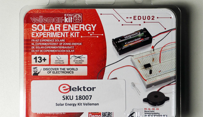
Solar Energy Experiment kit from Velleman
March 16, 2017
on
on

During a visit from some friends recently I was trying to think of some interesting activity for the older children who seemed to be looking a bit bored. It dawned on me that they were about the right age for the Velleman Solar Energy Experiment Kit I had bought recently. This seemed like a win-win situation, they would benefit from building the projects and I could write about how they got on with it… result! The prospect of actually making some physical experiments definitely got a positive reaction, they stopped swiping their screens… it looked like I had my volunteer guinea pigs.
Renewable sources of energy are the future while the energy demands of generations to come cannot be met indefinitely by burning fossil fuels. This seemed like the perfect opportunity to introduce the technology which will become increasingly more important in their future lives. There are probably many practicing engineers today whose interest in electronics was first sparked by tinkering with just such an experimenter’s kit in their youth.

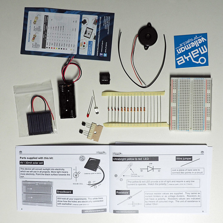
After unpacking the kit the first thing I noticed was a large colorful resistor color-code chart - in times of SMD components this is probably not so relevant for general use but the kit uses leaded devices and color-coded resistors (also included are short lengths of wire jumpers). The kit manual is extremely well organized with instructions for ten experiments which use solar energy to power electronic circuits. All the instructions are in English and the kit retails at a price of £19.95 for members.
The booklet starts out with a brief description of the components contained in the kit, from the solar cell via the function of a resistor, diode, Zener diode, LED, transistor, piezo transducer to the preprogrammed, eight-legged PIC10F220. These descriptions are quite important for the kit’s target audience, who otherwise would have more difficulty understanding how the individual circuits work. There are some extra components supplied in the kit than are strictly necessary to carry out all the experiments. In my kit there were more resistors, two transistors and twice the number of diodes required which is reassuring if anything gets broken or lost.

All experiments are carried out on the supplied prototyping plug-board. For each experiment there is a double-page spread with a schematic, a wiring layout as well as a functional description of the circuit. The series of projects begins with the simplest hardware experiment; to make an LED light up, equivalent to the ‘Hello World’ message for software projects.
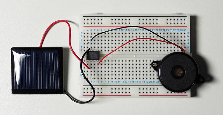
This circuit consists of a solar cell (by the way, a sample with eight subcells for a maximum of 5 V and a maximum of 30 mA), a series resistor and a red LED is, which of course is ultra simple, but at the start its probably more important for newbies to get quick success rather than achieve any great insights. After all, you could of course plug the LED in the wrong way round. For me, Experiment 1 was a success.
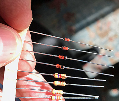
The experiments get progressively more complicated: from a microcontroller controlled flashing LED via a solar powered battery recharging station for two AAA NiMh rechargeable batteries (batteries are not included but the battery holder is), a light-dependent tone generator, which together with the piezo transducer builds a ‘playable’ solar musical instrument. Once they have gone through all the projects newbies will have gained the confidence to start playing around with their own designs. Luckily, young eyes are much better than mine at making out the small print on the diodes.
 NB: The microcontroller comes packaged in non-conductive foam but nowhere in the booklet is there any information on the correct handling of ICs. As a lifelong tinkerer I thought I might be able to help out here (and try to explain what a microcontroller actually is). It’s probably a good idea to stay on hand to help out when something is not clear for experimenters this young. There is no need to worry about the microcontroller being damaged by mistreatment, the solar cell supplies too little voltage and current to do any real harm. It should therefore be able to survive virtually any wiring mix ups.
Renewable sources of energy are the future while the energy demands of generations to come cannot be met indefinitely by burning fossil fuels. This seemed like the perfect opportunity to introduce the technology which will become increasingly more important in their future lives. There are probably many practicing engineers today whose interest in electronics was first sparked by tinkering with just such an experimenter’s kit in their youth.

After unpacking the kit the first thing I noticed was a large colorful resistor color-code chart - in times of SMD components this is probably not so relevant for general use but the kit uses leaded devices and color-coded resistors (also included are short lengths of wire jumpers). The kit manual is extremely well organized with instructions for ten experiments which use solar energy to power electronic circuits. All the instructions are in English and the kit retails at a price of £19.95 for members.
The booklet starts out with a brief description of the components contained in the kit, from the solar cell via the function of a resistor, diode, Zener diode, LED, transistor, piezo transducer to the preprogrammed, eight-legged PIC10F220. These descriptions are quite important for the kit’s target audience, who otherwise would have more difficulty understanding how the individual circuits work. There are some extra components supplied in the kit than are strictly necessary to carry out all the experiments. In my kit there were more resistors, two transistors and twice the number of diodes required which is reassuring if anything gets broken or lost.

All experiments are carried out on the supplied prototyping plug-board. For each experiment there is a double-page spread with a schematic, a wiring layout as well as a functional description of the circuit. The series of projects begins with the simplest hardware experiment; to make an LED light up, equivalent to the ‘Hello World’ message for software projects.
This circuit consists of a solar cell (by the way, a sample with eight subcells for a maximum of 5 V and a maximum of 30 mA), a series resistor and a red LED is, which of course is ultra simple, but at the start its probably more important for newbies to get quick success rather than achieve any great insights. After all, you could of course plug the LED in the wrong way round. For me, Experiment 1 was a success.
The experiments get progressively more complicated: from a microcontroller controlled flashing LED via a solar powered battery recharging station for two AAA NiMh rechargeable batteries (batteries are not included but the battery holder is), a light-dependent tone generator, which together with the piezo transducer builds a ‘playable’ solar musical instrument. Once they have gone through all the projects newbies will have gained the confidence to start playing around with their own designs. Luckily, young eyes are much better than mine at making out the small print on the diodes.
 NB: The microcontroller comes packaged in non-conductive foam but nowhere in the booklet is there any information on the correct handling of ICs. As a lifelong tinkerer I thought I might be able to help out here (and try to explain what a microcontroller actually is). It’s probably a good idea to stay on hand to help out when something is not clear for experimenters this young. There is no need to worry about the microcontroller being damaged by mistreatment, the solar cell supplies too little voltage and current to do any real harm. It should therefore be able to survive virtually any wiring mix ups.
Read full article
Hide full article


Discussion (0 comments)