

Sunlight-rejecting opto-switch
Light beams are useful for sensing in all kinds of applications - if other light sources, often sunlight, don’t interfere. Here’s one way.
Sunlight-rejecting opto-switch
Opto-switches using a light emitter and photosensitive detector are widely used for detecting position, counting events or determining rates of motion, but to operate correctly the detector must only respond to light produced by the emitter. In some applications, such as measuring the speed of a bicycle wheel, protecting the optical path from bright sunlight, spurious reflections or occasional sun glint may be difficult. If, however, the properties of the light in the opto-switch are made fundamentally different to daylight, for example in the wavelength of the light used or by modulating the optical signal in some way, the effect of daylight can be almost removed. The sun is, after all, other than the odd solar flare and 0.1% brightness variation during the solar cycle, essentially a dc source.
In this circuit, modulated infra-red light is used to provide an opto-switch for daylight use. It operates by comparing the signal transmitted with the signal received, assuming the optical path to be uninterrupted when both transmitted and received signals are identical. LED D1 and photodiode D2 provide and detect the signal respectively. Phase comparison of the two signals is conveniently achieved using one Exclusive-OR gate of a quad 4070 CMOS chip. For economy, the rest of the circuit is built around the three remaining Ex-OR gates in the same package, with easily obtained components.
Gates U1a and U1b are wired as inverters to form a standard CMOS two gate oscillator running at about 20 kHz [1], providing square wave drive to the infra-red emitter LED, D1. The received optical signal from photodiode D2 is ac-coupled to U1d, biased to operate as a linear amplifier. The amplified photodiode signal provides one input to phase detector U1c, and the LED drive signal (from U1b) the other. The output of U1c will go low if both digital inputs are the same, otherwise the output is non-zero, which, after the low-pass filter of R6 and C4, averages half the supply voltage. To provide clean switching transitions despite the charging and discharging of C4, a discrete Schmitt trigger circuit is added using transistors T1 and T2, which also lights an indicator LED D3 when the optical path is unobstructed. The final output is inverted with respect to the state of the LED.
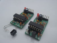
The circuit has been constructed using through-hole components on a small double-sided printed board. (SMD components would allow a more compact device for specific geometries). Photo-interrupter or photo-reflective modes can be used, as shown in the photograph left and right respectively. With a 940 nm wavelength IR LED, and a BPW34 photodiode, the opto-switch can operate in photo-interrupter mode over a 20 cm path in bright, but not direct, sunlight. In photo-reflective mode, the side-looking LED KM-4457F3C and photodiode BPW41N trigger reliably from a surface about 2 cm away, even the glass of a well-lit window.
Some of the component values can probably be further optimised. The essential requirement is to choose R4 so D2 does not saturate, to detect the small varying signal despite the steady sunlight. Measurements in direct sunlight with a BPW34 show that the junction of C3 and R4 is about 0.3 V, rising to about 4.2 V in the shade. Secondly, the 1 ms time constant of R6 and C4 affects the switching time, limiting the maximum switching frequency to about 100 Hz. Although the optical modulation frequency could be increased, increasing phase-lags around U1d will eventually prevent signal detection. Finally, note that the Schmitt thresholds have been designed for a 5 V supply, and will need adjustment for other supply voltages [2].
Is this best described as an analogue or digital circuit? Discuss...
References
[1] Horowitz P., and Hill W., The Art of Electronics, third edition, Cambridge University Press, (2015)
[2] http://www.johnhearfield.com/Eng/Schmitt.htm
Opto-switches using a light emitter and photosensitive detector are widely used for detecting position, counting events or determining rates of motion, but to operate correctly the detector must only respond to light produced by the emitter. In some applications, such as measuring the speed of a bicycle wheel, protecting the optical path from bright sunlight, spurious reflections or occasional sun glint may be difficult. If, however, the properties of the light in the opto-switch are made fundamentally different to daylight, for example in the wavelength of the light used or by modulating the optical signal in some way, the effect of daylight can be almost removed. The sun is, after all, other than the odd solar flare and 0.1% brightness variation during the solar cycle, essentially a dc source.
In this circuit, modulated infra-red light is used to provide an opto-switch for daylight use. It operates by comparing the signal transmitted with the signal received, assuming the optical path to be uninterrupted when both transmitted and received signals are identical. LED D1 and photodiode D2 provide and detect the signal respectively. Phase comparison of the two signals is conveniently achieved using one Exclusive-OR gate of a quad 4070 CMOS chip. For economy, the rest of the circuit is built around the three remaining Ex-OR gates in the same package, with easily obtained components.
Gates U1a and U1b are wired as inverters to form a standard CMOS two gate oscillator running at about 20 kHz [1], providing square wave drive to the infra-red emitter LED, D1. The received optical signal from photodiode D2 is ac-coupled to U1d, biased to operate as a linear amplifier. The amplified photodiode signal provides one input to phase detector U1c, and the LED drive signal (from U1b) the other. The output of U1c will go low if both digital inputs are the same, otherwise the output is non-zero, which, after the low-pass filter of R6 and C4, averages half the supply voltage. To provide clean switching transitions despite the charging and discharging of C4, a discrete Schmitt trigger circuit is added using transistors T1 and T2, which also lights an indicator LED D3 when the optical path is unobstructed. The final output is inverted with respect to the state of the LED.
The circuit has been constructed using through-hole components on a small double-sided printed board. (SMD components would allow a more compact device for specific geometries). Photo-interrupter or photo-reflective modes can be used, as shown in the photograph left and right respectively. With a 940 nm wavelength IR LED, and a BPW34 photodiode, the opto-switch can operate in photo-interrupter mode over a 20 cm path in bright, but not direct, sunlight. In photo-reflective mode, the side-looking LED KM-4457F3C and photodiode BPW41N trigger reliably from a surface about 2 cm away, even the glass of a well-lit window.
Some of the component values can probably be further optimised. The essential requirement is to choose R4 so D2 does not saturate, to detect the small varying signal despite the steady sunlight. Measurements in direct sunlight with a BPW34 show that the junction of C3 and R4 is about 0.3 V, rising to about 4.2 V in the shade. Secondly, the 1 ms time constant of R6 and C4 affects the switching time, limiting the maximum switching frequency to about 100 Hz. Although the optical modulation frequency could be increased, increasing phase-lags around U1d will eventually prevent signal detection. Finally, note that the Schmitt thresholds have been designed for a 5 V supply, and will need adjustment for other supply voltages [2].
Is this best described as an analogue or digital circuit? Discuss...
References
[1] Horowitz P., and Hill W., The Art of Electronics, third edition, Cambridge University Press, (2015)
[2] http://www.johnhearfield.com/Eng/Schmitt.htm
Updates from the author
LekkyTenore 5 years ago
ElektorLabs 5 years ago
LekkyTenore 5 years ago
Jörg Drobick 5 years ago
Dean 5 years ago
ANTONY 5 years ago
I found PLL based design is very simple with few components and more flexible and we can adopt to many applications with small form factor. The PLL IC can sink 100mA which is useful for driving small DIP Relay.
It worked well as diffuse scan sensor, retro reflective sensor and infrared beam interruption detector with ON/OFF delay
Transmitter power, operating frequency and loop filter can be easily designed with one or two component value change.
For additional improved performance we can use photo diode with inbuilt daylight cut-off filter or external filter sheet.
I have used this sensor as a non-contact tacho meter and tested upto 6000 RPM(Equvalent to 100Hz) without any issue. For faster response we need to reduce the loop filter component values.
For medium sensing range we can use photo transistor instead of photo diode for higher gain. Photo transistors are available with lens in TO18 package.
I have used fresnel lens sheet along with transimpedance amplifier TDA2320(Now Obsolete) for range upto 50m using single IR Tx LED. Since same PLL VCO oscillator frequency is used for both Tx and Rx there is no frequency drift issues.
Reference:
LM567C datasheet
TSL260 datasheet Figure 10. Proximity Detector
Mondo-tronics Modulated Infrared Reflective Detector #3-337
mondo-tronics-modulated-ir-detector.jpg (85kb)
ne567-tsl260.jpg (102kb)
q1-photodiode-daylight-cutoff.jpg (262kb)
tda2320.JPG (274kb)
LekkyTenore 5 years ago