

Vacuum Tube Curve Tracer: remake of Tektronix 570
Measure vacuum tubes (triodes, pentodes) as they did in the 1950's with a remake of the Tektronix 570 "Characteristic Curve Tracer".
I have a heap of vacuum tubes lying around for years that I took from tv's and radios in the previous century. They just sit there gathering dust and I don't know if they are any good anyway. Curious to see if they're worth anything, I looked up a few on Ebay. I hit upon a seller from France that accompanies each vacuum tube with a photo of its "characteristic curve", which he makes with an old Tektronix 570 Characteristic Curve Tracer. Search for "Tektronix 570" on Ebay.
This tube tester successively applies several different grid voltages (0V, -1V, -2V, etc) and then varies the plate (anode) voltage from zero to a couple hundred volt. Plate current is drawn against plate voltage. In this way a handful of graphs is automatically displayed on an oscilloscope screen.
I want to have that too!
The Tek570 was a huge machine weighing 75 pounds, 42 cm high, 33cm wide and 62cm deep. With modern electronics, I'm sure I can do this at a fraction of the weight. I'll use an existing oscilloscope. Maybe later, I can even measure things like transconductivity etc. automatically and display all that on an LCD display or something. But let's start with the Neptronix 570!
My design
I am using an ATMEGA32 because it has lots of I/O ports, is available in DIP, is cheap and I have several of them lying around. The only drawback is that it doesn't have a digital to analog converter (DAC), so I'm using a two-output AD7302. Disadvantage is that it is no longer available in DIP (at least for a reasonable price), but in 0.05" grid SMD package, so I have to solder it on a small converter board to be able to put it on a breadboard. The 8 bit wide parallel interface is very convenient from a firmware standpoint.
Grid
The microcontroller and the DAC co-operate to put a voltage on output B of the DAC that goes up stepwise from 0V in 20 steps of 10/256*5V up to 3.9V. As the grid voltage needs to be negative, I convert the 0-3.9V output from output B of the DAC to minus20-0V with opamp IC3A. I added R9 and R10 later to do fine adjustment of the delta between each step (1 volt) and the offset. Opamp IC3B was also added later and is explained below.
Plate
The plate voltage has to go up to +300V. First, opamp IC2A amplifies output A of the DAC 3 times and adds 2.4 volts. Then T2 does an amplification of -16. T3 is an emitter follower to increase the current. T2 and T3 are MPSA42, which can withstand up to 300V. Whereas the grid voltage has to be exact in steps from 0V, -1V, -2V, etc., the plate voltage doesn't need to be exact, it sweeps from about 50 to about 300V and is being plotted on the oscilloscope screen. There is a switchable resistor in the plate circuit, which limits current and power dissipated in the tube and is copied as-is from the Tek 570.
Kathode
In order to be able to measure the kathode current, R26 is placed between kathode and ground. To compensate for the voltage drop across this resistor, IC3B adds the kathode voltage to the output voltage of IC3A. The result is given to the grid.
Supply
The following supply voltages are needed:
I generate the +320V with an MC34063, a mosfet and a power inductor. For the -20V I used a buck converter with mosfets and capacitors, connected to some free ports of the microcontroller, but later I removed that again.
Results
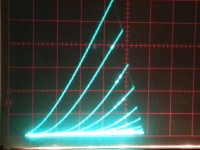
The graph that accompanies this article was produced with this circuit. So it works! As an experiment, I wanted to indicate visually in the graphs which one is the -1V, which one the -2V, etc. If you look closely, you will see one or more bright spots in the graphs which indicate just that! This was done by connecting the brightness (z) input of the oscilloscope to PD3.
Future plans
I suspect the the LM358's are a bit too slow to generate a clean step function. Maybe I'll replace them with something faster. Any suggestions?
I also want to be able to draw a graph of kathode current against grid voltage, with stepping plate voltage. For this to be of any use, the plate voltage needs to be controlled exactly. The current circuit is not able to generate a reliable step voltage on the plate output, there are lots of ringing and other unreliable behaviour when I try to do that. I'm open for suggestions how to improve the plate circuit.
Also the grid circuit is not perfect. I would want to get rid of those nasty potmeters. Any suggestions?
I want to be able to test pentodes. They need yet another supply voltage for grid 2. Or one can tie g2 to the anode.
It would be nice to use the Analog inputs of the ATmega to measure the voltages and show the results an a graphic LCD display. Then we could measure really slowly, eliminating any AC behaviour. We could do without an oscilloscope. Or measure and playback on a scope anyway!
This tube tester successively applies several different grid voltages (0V, -1V, -2V, etc) and then varies the plate (anode) voltage from zero to a couple hundred volt. Plate current is drawn against plate voltage. In this way a handful of graphs is automatically displayed on an oscilloscope screen.
I want to have that too!
The Tek570 was a huge machine weighing 75 pounds, 42 cm high, 33cm wide and 62cm deep. With modern electronics, I'm sure I can do this at a fraction of the weight. I'll use an existing oscilloscope. Maybe later, I can even measure things like transconductivity etc. automatically and display all that on an LCD display or something. But let's start with the Neptronix 570!
My design
I am using an ATMEGA32 because it has lots of I/O ports, is available in DIP, is cheap and I have several of them lying around. The only drawback is that it doesn't have a digital to analog converter (DAC), so I'm using a two-output AD7302. Disadvantage is that it is no longer available in DIP (at least for a reasonable price), but in 0.05" grid SMD package, so I have to solder it on a small converter board to be able to put it on a breadboard. The 8 bit wide parallel interface is very convenient from a firmware standpoint.
Grid
The microcontroller and the DAC co-operate to put a voltage on output B of the DAC that goes up stepwise from 0V in 20 steps of 10/256*5V up to 3.9V. As the grid voltage needs to be negative, I convert the 0-3.9V output from output B of the DAC to minus20-0V with opamp IC3A. I added R9 and R10 later to do fine adjustment of the delta between each step (1 volt) and the offset. Opamp IC3B was also added later and is explained below.
Plate
The plate voltage has to go up to +300V. First, opamp IC2A amplifies output A of the DAC 3 times and adds 2.4 volts. Then T2 does an amplification of -16. T3 is an emitter follower to increase the current. T2 and T3 are MPSA42, which can withstand up to 300V. Whereas the grid voltage has to be exact in steps from 0V, -1V, -2V, etc., the plate voltage doesn't need to be exact, it sweeps from about 50 to about 300V and is being plotted on the oscilloscope screen. There is a switchable resistor in the plate circuit, which limits current and power dissipated in the tube and is copied as-is from the Tek 570.
Kathode
In order to be able to measure the kathode current, R26 is placed between kathode and ground. To compensate for the voltage drop across this resistor, IC3B adds the kathode voltage to the output voltage of IC3A. The result is given to the grid.
Supply
The following supply voltages are needed:
- +5V for the ATMega and the DAC
- +20V for IC2
- +320V for the MPSA42's to generate the plate voltage
- -20V for IC3A to generate the grid voltage
- Heater voltage, depending on the tube used.
I generate the +320V with an MC34063, a mosfet and a power inductor. For the -20V I used a buck converter with mosfets and capacitors, connected to some free ports of the microcontroller, but later I removed that again.
Results
The graph that accompanies this article was produced with this circuit. So it works! As an experiment, I wanted to indicate visually in the graphs which one is the -1V, which one the -2V, etc. If you look closely, you will see one or more bright spots in the graphs which indicate just that! This was done by connecting the brightness (z) input of the oscilloscope to PD3.
Future plans
I suspect the the LM358's are a bit too slow to generate a clean step function. Maybe I'll replace them with something faster. Any suggestions?
I also want to be able to draw a graph of kathode current against grid voltage, with stepping plate voltage. For this to be of any use, the plate voltage needs to be controlled exactly. The current circuit is not able to generate a reliable step voltage on the plate output, there are lots of ringing and other unreliable behaviour when I try to do that. I'm open for suggestions how to improve the plate circuit.
Also the grid circuit is not perfect. I would want to get rid of those nasty potmeters. Any suggestions?
I want to be able to test pentodes. They need yet another supply voltage for grid 2. Or one can tie g2 to the anode.
It would be nice to use the Analog inputs of the ATmega to measure the voltages and show the results an a graphic LCD display. Then we could measure really slowly, eliminating any AC behaviour. We could do without an oscilloscope. Or measure and playback on a scope anyway!
Discussion (3 comments)


Robert Wagner 8 years ago
Hello, i am Robert, from germany and i am also working already for some time on a similar design, but with fully automated tests and recognition of "unknown" tubes due to initial "cold"-tests and a measurement matrix which is able to deliver almost any voltage/current at any pin...
My base was one of the famous "Neuberger" tube testers from WWII and the decade after, which i wanted to rebuild with modern electronics in a "solid state" version, so without any mechanical switches, jump-wires or something alike.
It should work for the most popular sockets of "post WWII" tubes, but also be able to adopt to any socket else.
As it can not only supply a fixed test voltage, but run through the complete range, it can also be used as a curve-tracer so far, my intention was to build a library of "characteristical data" over all available tubes to be able to do the detection and "matching" of unknown tubes or unknown "health"/operational hours of similar tubes.
As i am a fully working guy in medium age (father of 3 kids) my time for hobbyist projects is very restricted, but maybe we could combine those projects and then share the work over some more interested guys?
I have "some" private lab with lots of measurement/test devices and also PCB-milling and smd-population-tools, so i can support a lot.
best regards,
Robert
PS: you can reach me via wagner_rob@gmx.de write "tube-tester" in the title, so that it will not be blocked by spam-filtering.
Reply

cvdo 8 years ago
Hi Robert,
Sounds like an ambitious project you're up to. I have been thinking dreaming about automatic determination, but I feared it would require lots and lots of components to be able to sense all the pins and apply all voltages, from heater voltage (with large current) to high voltage on the anode. I'm curious to see your matrix schematic up to now. And how can you protect the tube under test from being blown up while testing it?
First thing is to find out where the heater connections are. That's the easy part. Then, how much power to apply to the heater? You could make use of the effect that the resistance drops as the temperatore rises, but I guess not all tubes operate at the same temperature.
Similar problems arise when determining a sensible voltage and current for the plate. Some tubes work at 500V while e.g. the 12EL6 is designed for 12.6V plate voltage and has an absolute maximum of 30V.
Reply
Show more
1 Comment(s)

Updates from the author
cvdo 7 years ago
If you plan to build this project yourself, be aware of the following. I am using a graphic LCD display that is currently not easy to obtain. Therefore, I am now making an alternative version that is based on a 4 line text LCD, which are for sale anywhere. The schematic is exactly the same, the graphic LCD is just replaced by a text LCD, 8 lines parallel data plus enable and data/command.
I will attach Neptronics0.6.zip to this post with the firmware, which is working except for the automated transconductance measurement, which is not implemented yet.
cvdo 8 years ago
I made a small test setup and wrote a program for both the SPI DAC and the parallel DAC. Both programs generate a sawtooth on their output A, using all 256 possible values. The results are as follows. The SPI DAC (MCP4902) generates a sawtooth at 532 Hz. The parallel DAC (AD7302) generates a sawtooth at 3300 Hz. That is 6.2 x as fast!
So back to the AD7302. Disadvantage is that it is only available in SMD form, but OK. It's 1.27mm pitch, so not too bad. The fact that it uses 10 IO-ports is not that bad, because it can share the 8 bit data bus with the LCD that I'm using.
Attached is the latest schematic diagram.
cvdo 8 years ago
- to set the minimum and maximum anode voltage
- to set the minimum and maximum grid voltage
- to choose between: step grid and sweep anode or v.v.
- to set the step voltage
- to start and stop a measurement
and maybe:
- to set heater voltage and current
- set set maximum anode current and/or power dissipated in the tube
I have been doubting for a long time wether to make this with old fashioned rotating knobs (like the original Tektronix) or with an LCD and push buttons. Finally I decided to cut the knot and to go for an LCD. Mainly because it is easily extensible and easier to build, less wiring etc.
The LCD whows a number of tabs. On each tab there are related settings e.g. all the anode settings). There are four arrow buttons to navigate through the tabs. It works great! I made a Youtube film to show the idea: https://youtu.be/GQAonn2gi8o
I made the film when I had the rough idea for the user interface, but it wasn't doing anything actually. During the last days I have been working on that. At the moment, all the functions are working.
Today I'm struggling with the analogue circuitry. Things like feedback, interference, noise and so on. The anode output circuit now has a feedback loop, to be able to precisely control anode voltage. Maybe I should revert to the original circuit with the plain transistor no-feedback anode circuit.
State of the art ;-) (1451kb)
cvdo 8 years ago
The new setup uses:
On the photograph I am testing one of the triodes of an ECC85. Four graphs are drawn. The top one is for Vg=0V, the Vg=-1V, -2V and -3V. On the horizontal axis: Vanode, max is 150V. On the vertical axis: Ikathode, maximum is 6mA.
What's the conclusion? The original idea, with the oscilloscope looked much better than this cheap LCD stuff. However, I can easily modify the current setup to draw other graphs (Ikathode vs. Vg). Maybe I should make the best of both worlds. Add a second DAC that sends synthesized results to an oscilloscope...
20170114-215434.jpg (2936kb)
20170114-215434-kopie.jpg (507kb)
cvdo 8 years ago
My theory is that a high voltage found its way through to g1, into the op-amp, onto the +5V rail and into the DAC. I should have put some form of protection on g1 and on the +5V rail. And don't connect the op-amp to the same 5V as the DAC and microcontroller, give them separate supplies. Lesson learned.
Unfortunately, I do not have the same DAC at hand to repair everything. So I decided to order new AD7302 DAC's and in the mean time start over with a fresh idea. I am using a DAC with SPI now (MCP4902), an ATMEGA328 and an LCD display. No scope needed. Working on that now.
Schematic - No high voltages yet - just measuring an 1N4148 (108kb)
cvdo 8 years ago
I want to use this to make kathode current vs. gate voltage diagrams with constant values of Vplate.
The firmware takes care that the digital value on the DAC is 0, 50, 100, 150, 200, 250. This resultst in analog values of 0V, 0.97V...4.88V. After multiplication by 30, this gives a theoretical stepping plate voltage of 0, 26V, 52V, 78V, 117V, 146V.
I have added an oscilloscope screenshot of Vplate and Vgate in time, which shows that the 0V is not quite reached and there is a strange glitch between 0V and 26V. And what should be 146V, is in reality more like 140V. But for the rest, the stepping function seems to work OK.
The result is the desired set of six graphs. See attached photo. The steepest graph is 2mA/0.8V=2.5mA/V. According to the datasheet, it should be 5.8mA/V, so...
Graph in the datasheet of the PCF82 (triode) (122kb)
Scope images (2165kb)
Grid voltage (top) and plate voltage (bottom) in time (1411kb)
Kathode current vs. grid voltage (924kb)
cvdo 8 years ago
cvdo 8 years ago
The output of the DAC jumps is a stepped sawtooth. When it is at the end of its sawtooth it flips from 0 to 3.8V in 0.5us according to my scope. This is at the limit of my HM305 scope to measure accurately. According to the datasheet of the AD7302 it has a typical slew rate of 7.5V/us, so that 0.5us might be spot on.
After IC3a (LM358) it takes 30us to reach the final value. After IC3b, it's even 1 or 2us more.
When I replace IC3 by the NE5532, it takes 11us to do the same thing. That's almost 3 times as good!
P.S. I was trying to find out how old these op amps really are but it seems impossible to find any information on the Internet. I looked them up in old De Katalogus from Display Elektronika from 1982/83 and it states the LM358 (for f. 1,90) but not the NE5532.
There is an application note for the LM358 from 1980. And this datasheet refers to june 1976. That'll be it for the LM358. The NE5532 dates from 1979 according to this datasheet.
CopterCarl 8 years ago
I could make an alternative suggestion:
OPA 2132 (s. attachment).
It can handle 36V and is fast enough.
You can have 2 OPs from me. I have some left.
Best Regards
Carl
cvdo 8 years ago
On second thoughts, the NE5532 takes up to twice 22V (The TI datasheet is clearer about this than Fairchild's), so I need not worry about it. Although it does have another problem. The NE5532 is not rail to rail, which I found out when I replaced also IC2. I'll have to give it a negative supply of -5V or so to fix that. When I look at the datasheet of the OPA2132, it goes from V- + 2.5V to V+ - 2.5V, same problem. Apparently the LM358 did better in that aspect?
Maybe try MC33078.