

Z79Forth Reference Board
Forth like it's 1979 all over again!
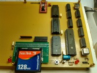
This platform is designed as a basis for self-education and further hardware development. The target Forth variant is the 79-STANDARD, an historic reference. The whole design is based on the Hitachi HD63C09E--a much improved implementation of the Motorola MC6809.
Main features are:
The software is licensed under the GNU General Public License version 3 and is available at https://github.com/frenchie68/Z79Forth. Kicad schematics are also provided over there.
Project status: working wire wrapped prototype. The software itself is believed to perform according to specifications. There are no known bugs at this time.
Main features are:
- 5 MHz CPU operation.
- 32 KB static RAM. Conceivably expandable to 48 KB.
- 8 KB EEPROM running a native 79-STANDARD Forth sub-set implementation.
- 6 spare IO device lines are decoded and available for further developments.
- USB powered. The current consumption is somewhere between 56 and 150 mA.
- Serial line console operating at 115200 bps.
- Mass storage support on SanDisk CompactFlash (up to 64 MB).
- Interrupt free design.
The software is licensed under the GNU General Public License version 3 and is available at https://github.com/frenchie68/Z79Forth. Kicad schematics are also provided over there.
Project status: working wire wrapped prototype. The software itself is believed to perform according to specifications. There are no known bugs at this time.
Discussion (8 comments)
lux36 1 year ago
You might like my "retro" Z80 project as well...
https://www.elektormagazine.com/labs/crypto-dev-shield-for-zmc-zilog-z80-system-1
https://www.elektormagazine.com/labs/crypto-dev-shield-for-zmc-zilog-z80-system-1
Reply
Show more
0 Comment(s)

Johnny Quest 4 years ago
Hello Francois:
Great project! I too love working with "vintage 8-bit" CPUs and MCUs. I have lots of vintage parts in DIP packages from the 70's, 80's and 90's. The hardware was SO MUCH easier to troubleshoot back then. However, with the on-chip debugging interfaces of today, software development is easier.
I was wondering why your hardware doesn't support interrupts.
In one project I worked on, an 8085SBC developed by Martin Maly from Czechia (https://hackaday.com/2018/08/20/omen-alpha-a-diy-8085-based-computer), it used an MC68B50 ACIA as does your project. I had some issues with the ACIA missing received characters while continuously pumping out characters. Seems the RDRF flag is NOT independent of the TDRE flag and is reset when the TDRE bit is set by the hardware, which can cause the polling software to miss incoming characters. I determined it to be a hardware issue in the MC68B50. The HITACHI version is the HD63B50, which has the same bug. I detailed the issue in this post https://8085sbc.wordpress.com/2018/10/17/testing-the-mon85-firmware-on-the-omen-alpha.
Peace and blessings,
JQ
Reply

f.laagel@ieee.org 4 years ago
Hi Johnny,
I wanted to keep the design as simple as possible. You are absolutely right, with no interrupts, characters might be lost on input and there is really no way around that fact. This is mostly annoying when resorting to cut and paste--the kind of facility you really need when you want to do things like bootstrapping the editor!
There are, however, ways to mitigate this deficiency. I for one introduce extra delays in the Minicom output delay parameters. ^AZTD 20 (20 ms wait after CR output) and ^AZTF 2 (2ms after each character output) work for me most of the time.
Also, I make heavy use of the 6309 extended instruction set. One of these instructions is TFM (transfer from memory), which is reminiscent of the Z80 LDIR instruction. This is great for memory block moves and increased IO rates to/from the CompactFlash module. But there is a catch. That instruction, which I use on 43 instances, is the only one that is interruptible. The 6309 has a one byte memory cache whose contents might be lost, should an interrupt occur during a transfer. As a result, enabling interrupts would require all those 43 references to TFM to be protected. I do not have enough EEPROM (8KB) space to do that.
Also, the Z79Forth reference board uses an HD63B50, not the 68B50. A possible difference between these two is that the HD63B50 does not require a clock on its E input. It can also function with a strobe pulse. I do not know for a fact that the 68B50 can operate properly in these conditions.
Additionally, I strongly suspect that the loss of characters is not due to a weird coupling between the RDRF and TDRE flags of the ACIA. To me, the root cause for this is with the FTDI-232RL module in front of it. FTDI's FAQ (https://www.ftdichip.com/Support/FAQs.htm), under section "How does RTS/CTS flow control work in an FTDI chip?" states:
"If CTS# is logic 1 it is indicating the external device cannot accept more data. the FTxxx will stop transmitting within 0~3 characters, depending on what is in the buffer.
This potential 3 character overrun does occasionally present problems. Customers should be made aware the FTxxx is a USB device and not a 'normal' RS232 device as seen on a PC. As such the device operates on a packet basis as opposed to a byte basis."
All the best.
Francois
Reply
Johnny Quest 4 years ago
Hi Francois:
Thanks for your response.
If you re-read my post and look at my blog post (link included in my post) where I tested the MOTOROLA MC68B50 AND the HITACHI HD63B50 (and laid out my testing procedure and results), they both have the hardware bug with the RDRF and TDRE flags, so HITACHI must have simply used the original die layout to be a 2nd source.
Thanks for the explanation about the USB-2-TTL converters. I am aware that they are packet-based devices.
Peace and blessings,
Johnny
Reply
Show more
1 Comment(s)

f4dui 4 years ago
j'avais mis le forth sur un kit 68000 motorola c'étais du paperware en hexa de ce temps.
tres rapide existe sur arduino.
tres rapide existe sur arduino.
Reply
f.laagel@ieee.org 4 years ago
Salut f4dui,
Durant mes tendres annees (j'avais 19 ans), j'ai egalement code pour le 6800 en hexadecimal. Nous n'avions meme pas le luxe d'avoir un assembleur--ou meme un frontal de developement. C'etait ma premiere annee d'IUT GEII. Nostalgie, nostalgie...
Bien a vous.
Francois
Durant mes tendres annees (j'avais 19 ans), j'ai egalement code pour le 6800 en hexadecimal. Nous n'avions meme pas le luxe d'avoir un assembleur--ou meme un frontal de developement. C'etait ma premiere annee d'IUT GEII. Nostalgie, nostalgie...
Bien a vous.
Francois
Reply
Show more
1 Comment(s)


Doug Jackson 4 years ago
This reminds me of the hours I spent at uni, loading Fig Forth into a Z80 based STD bus board.
Hours of fun.
I like your use of a CF card, and a 63C09 CPU - Very tidy. I might just have to do a small Mouser order :-)
Thank you.
Hours of fun.
I like your use of a CF card, and a 63C09 CPU - Very tidy. I might just have to do a small Mouser order :-)
Thank you.
Reply
f.laagel@ieee.org 4 years ago
Be aware that the design presented here is the result of evolutionary experience. I initially meant the CompactFlash module to interface directly with the processor's data bus. But I started out using Transcend CF cards and never was able to read anything from those besides zeroes. This is when I added the CD74HCT245 bidirectional buffer and still had no luck with the Transcend cards. Later on I switched to SanDisk and finally things began to work as expected. Ultimately I added the pulldown resistor network so as to simplify the "card present" detection code by having a predictable state when no card is inserted. This saves between 30 to 40 bytes of EEPROM storage. But then again, when you're doing 8 bit computing, every single byte matters!
I hope you will be able to purchase most of the required components from Mouser (especially the wire wrapping sockets). In my experience, this has proved tricky and I had to resort to Ebay more often than not.
I hope you will be able to purchase most of the required components from Mouser (especially the wire wrapping sockets). In my experience, this has proved tricky and I had to resort to Ebay more often than not.
Reply
Show more
1 Comment(s)
Updates from the author
f.laagel@ieee.org 2 years ago
f.laagel@ieee.org 3 years ago
Stay tuned...
f.laagel@ieee.org 3 years ago
See https://github.com/frenchie68/Z79Forth/releases/tag/REL-2.0 for up to date material.
The files available on ElektorLabs no longer are relevant.
f.laagel@ieee.org 3 years ago
GuusAssmann 3 years ago
Just now I've read this message.
I have designed a PCB for your project, using Ki-Cad.
It has already been produced and I've build one prototype. Not tested yet due to lack of a CPU and time.
Send me a mailaddress and I'll foreward the complete design files and some information.
Mail to: guus.assmann(at)wolmail.nl
f.laagel@ieee.org 3 years ago
We have been in touch via alternate channels and I had a chance to have a glimpse at your output. I wish to say here, for the record, that I am impressed by the result. Sure, it is an RS232 only device and it requires a regulated 5V input but besides that, I find it extremely cool.
In essence, if we could agree on interrupt handling details, I would most likely use your design as a basis for the kit--and tell my hardware guy that, somehow, he has been outgunned ;-)
One more thing I thought was missing in the original design is some sort of a configuration register. An array of straps that could be read by the processor and would be used to customize the serial line operational parameters. Do you support a similar functionality?
Best regards.
Francois
GuusAssmann 3 years ago
First of all, thanks for a nice design.
And as I wrote, I'd rather say that I provided your hardware guy with a flying start.
Once we know my PCB is running, with an extra wire for the IRQ, some improvements can be discussed and tested.
My PCB is 100 x 100 mm and those can be had at very low prices. And I like making a PCB design more than using wire-wrap or other methods. But that's just a matter of taste.
For the configuration, I've sent you a suggestion. In short, it may be possible to use the CF-card to do that. It has a name or maybe some bytes in the MBR.
The card has an edge connector that will fit in the bus-system made by Craig Andrews.
Have a look at https://sbc-85.com/ for more information on this.
Some more cards are available or in development.
BR/
Guus Assmann
f.laagel@ieee.org 3 years ago
In the continued absence of feedback from Elektor's editors, it looks like if I want to make this project a reality for the masses, I will have to go it by myself. Which is something I am willing to do. To that extent, I would like to develop a kit version of the platform. That particular implementation would have additional features that the publicly available design does not support. For all of these objectives to come to fruition, I am in the market for an electronics design engineer with a background in product development. The ultimate target has yet to be finalized but a set of goals for it have been defined already.
Anyone interested by the offer should be able to:
- fix the electrical deficiencies in he original design.
- work out a PCB design from schematics.
- figure out precisely which components are adequate in order to achieve the minimum manufacturing cost. Component sourcing/selection might also be a part of the job.
The work on this will be pro bono. The benefits, if any, will be shared.
Throwing a message bottle into the ocean...
f.laagel@ieee.org 4 years ago
f.laagel@ieee.org 4 years ago
I apologize for the inconvenience.
This has now been corrected in the PDF 2.1 version and in the Kicad 5.1.8 Eeschema material.
The github stuff also has been updated.