
Review: Assemble your own Mendocino Solar Motor
should produce a short-circuit condition
but only one of the two cells will
have light falling on it.
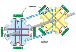
Construction of the octogonal Mendocino motor
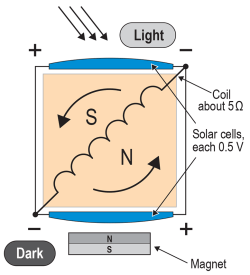
There are eight solar cells arranged edge to edge to form the rotor. One cell will be illuminated while its opposite will be in the shade. The two cells are wired in series which would seem to present a short circuit to the voltage generated. In practice however it doesn’t cause a problem because one of the cells will be in the shade whilst its partner will be in full sun. The cell facing the light produces a voltage while the cell in the shade acts as a relatively high impedance. Current therefore flows through the coil. After the rotor has rotated through 180˚ the coil has turned around so that the energy pulse supplied by the opposite cell (which now faces the light) is of the correct polarity to reinforce the rotor’s spin.A quick succession of pulses
We use 65 x 20 mm sized solar cells which have a maximum output voltage of 0.5 V. The magnetic field strength produced by a coil can be calculated as the product of the number of turns and the current flowing. To get a high value of current flowing it’s necessary to ensure low resistance of the coil.The coil winding has a DC resistance of around 5 Ω. Current in the coil is given by the voltage divided by the resistance:
I = V/R = 0.5/5 = 100 mA.
turns of 0.3 mm diameter (AWG 28) wire.
The coils in the rotor assembly fit underneath the solar cells and are the same width as the drive magnet in the frame. They are positioned directly behind the solar cells and are therefore positioned optimally in the magnetic field. In contrast to other motor designs where the coils are positioned parallel to the cells and are visible, the wire length in this design is reduced which has a beneficial influence on current flow.
1000 rpm in full sun
described in the provided assembly instructions.
Read full article
Hide full article
Discussion (3 comments)