

Review: SmartPi – smart meter extension for Raspberry Pi
Connecting the SmartPi to a network
The SmartPi exposes all the RPi connectors, including the Ethernet connector. After cabling the SmartPi to my router it showed up in its DHCP client list; point a browser to port 1080 at this address and the SmartPi user interface appears.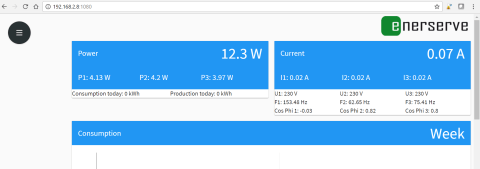
Unfortunately my router is located far away from the electrical switchboard, so Wi-Fi would be handy. How to do this or even if this is possible is not mentioned anywhere. The RPi 3 ships with Wi-Fi, so I decided to configure it over SSH (username and password are mentioned in the manual) and see if it would work.
SmartPi & Wi-Fi
Connect to the SmartPi over SSH with PuTTY (or some other SSH client) and edit the file ‘wpa_supplicant.conf’ using the commandsudo nano /etc/wpa_supplicant/wpa_supplicant.confAdd the following at the end of the file (replacing mySSID & myPassPhrase by your SSID & your pass phrase):
network={
    ssid="mySSID"
    psk="myPassPhrase"
    key_mgmt=WPA-PSK
}
Press Ctrl-O followed by the Enter key to save the file, press Ctrl-X to quit the editor. Disconnect the Ethernet cable and reboot the SmartPi. Now it is accessible over Wi-Fi. (Why on earth didn’t they document this?)
Change the SmartPi password
Now that we are busy setting up the RPi, we might as well change the password. To do so is highly recommended by the SmartPi people, but, again, how to do this is not explained. Here is the secret. Launch the SSH client (again) and connect to the SmartPi, then launch the Raspberry Pi configuration tool with:sudo raspi-configSelect ‘Change User Password’ and enter a new password.
Connecting the mains to the SmartPi
Once more, the documentation is not very helpful. How the SmartPi’s inputs correspond to the phases and neutral is neither printed on the SmartPi nor in the manual, but luckily the website has photographs with labelled inputs.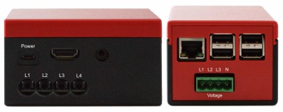
The evaluation SmartPi came with three current sensors. My home has a single-phase mains network. The switchbox has two groups, and so I put a current sensor on each group. The third sensor was clamped on the wire going to the water heater (in the second group). I connected the three voltage inputs together and wired them to a fuse.
Read full article
Hide full article
Discussion (5 comments)
Michael Collins 7 years ago
Using the optical port you get exact digital readouts directly from the meter, for all phases, etc.
I got my Optical probe for $45 from eBay:
http://www.ebay.co.uk/itm/201986568104
and as it has USB and serial options it is compatible with all operating systems as well as RPi.
eduino.io #oetelx 7 years ago
How does it work?
Where is the schematic?
What do I learn from this project?
It is Elektor, so I should be able to learn something...
It it even safe or legal to attach such a device to the power grid?
If I do so, will my house still be coverered by insurance?
Does this thing have any certifications?
The picture of the setup looks like an accident waiting to happen, no little kids in the house I presume.
Could I not better connect a optical insulated P1 port reader to my smart meter to collect data? (no need for backup batteries)
No trying to be negative here but I am not seeing it as an Elektor project.
ClemensValens 7 years ago
eduino.io #oetelx 7 years ago
device for measurement, maybe that is the reason you can not use the current sensors for 3 separate measurements of the same phase?
Maybe you can add some high resolution images so we can see what is actualy on the circuit board.
I also can not find out if you used the version 1 or 2, some picture is from version 1 but the shop has version 2.
ClemensValens 7 years ago