The µTracer tube tester kit. Part 2: assembly, step by step
April 06, 2017
on
on

In this short series of blogs I am reporting on my progress with assembling and using the µTracer 3+ vacuum tube curve tracer kit from DOS4EVER. The previous installment was published in Elektor e-zine no. 216 and the article may be found here. I have no commercial connection with DOS4EVER and purchased my kit.
Here is part 2. I was delighted to see the response to Part 1 of this blog-style sequel, the view rates and subsequent comments were very good and encouraged me continue with the series.
I daresay I am reasonably advanced in electronics assembly and have constructed and repaired many circuits especially RF and tubes but also digital. I really enjoy assembling kits and have come to value their makers not just for the end result but also for the educational aspects and the accuracy of the assembly instructions in particular. In the past as a licenced ham I personally organized several personal mobile radio conversion kits (Philips FM1000 and MX294) which sold in the hundreds globally, and found that making a good kit goes way beyond popping a few thousand electronic and mechanical parts in plastic bags.
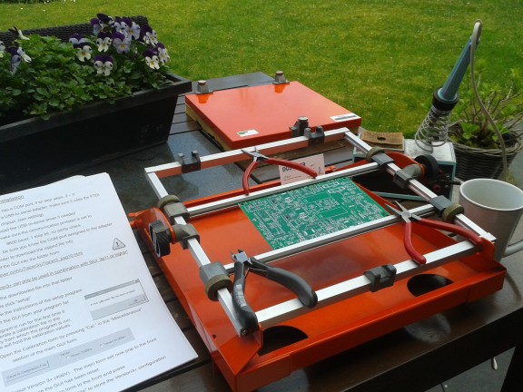
 Among the things a supplier of whichever kit for home assembly cannot possibly know or gauge is (a) your skills, (b) your tools and (c) your patience. Personally I am very fond of some of my tools including basic ones like a 1985 Weller Magnastat 50-watt solder station, and a set of high quality pliers and cutters. To which I recently added a bright orange PCB assembly fixture on loan from my colleagues in the labs.
For the actual board assembly, i.e. mounting parts on the µTracer PCB and soldering them, I was happy to discover that the excellently manufactured board in the µTracer kit comes with the PGA113 ICs already mounted. These are tiny MSOP-10 devices that are a challenge to mount manually and I applaud Ronal Dekker’s persistence in using them as they are perfect for their task — and simply not available in any sort of DIP case!
Here is part 2. I was delighted to see the response to Part 1 of this blog-style sequel, the view rates and subsequent comments were very good and encouraged me continue with the series.
I daresay I am reasonably advanced in electronics assembly and have constructed and repaired many circuits especially RF and tubes but also digital. I really enjoy assembling kits and have come to value their makers not just for the end result but also for the educational aspects and the accuracy of the assembly instructions in particular. In the past as a licenced ham I personally organized several personal mobile radio conversion kits (Philips FM1000 and MX294) which sold in the hundreds globally, and found that making a good kit goes way beyond popping a few thousand electronic and mechanical parts in plastic bags.
 Among the things a supplier of whichever kit for home assembly cannot possibly know or gauge is (a) your skills, (b) your tools and (c) your patience. Personally I am very fond of some of my tools including basic ones like a 1985 Weller Magnastat 50-watt solder station, and a set of high quality pliers and cutters. To which I recently added a bright orange PCB assembly fixture on loan from my colleagues in the labs.
For the actual board assembly, i.e. mounting parts on the µTracer PCB and soldering them, I was happy to discover that the excellently manufactured board in the µTracer kit comes with the PGA113 ICs already mounted. These are tiny MSOP-10 devices that are a challenge to mount manually and I applaud Ronal Dekker’s persistence in using them as they are perfect for their task — and simply not available in any sort of DIP case!
Software first
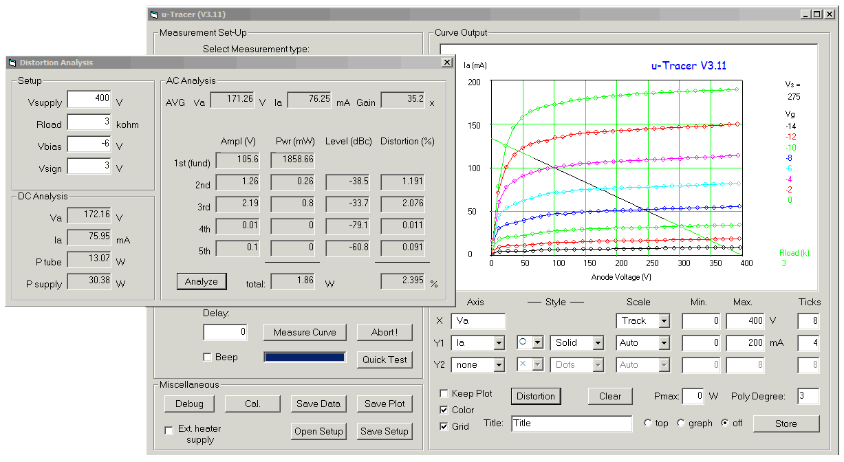
As is the custom with devices talking USB (in essence), the µTracer Construction Manual commences with the installation of the GUI (graphical user interface) and its pathway to the µTracer board through a USB-to-serial adapter.Read full article
Hide full article


Discussion (0 comments)