Article
3-Way Display Alarm
with 2.2-inch TFT screen

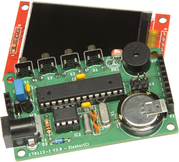
They say “Curiosity killed the cat”, as if it were some kind of undesirable character defect. But I see it more as a positive quality, essential in technical fields. Digging around, going off in search of a specific characteristic… Quite by accident, on the web I came across a little 2.2-inch diagonal TFT screen (and all its larger fellows). I felt an irresistible urge to heat up the soldering iron and take advantage of its display capabilities (text and graphics). What’s more, I still hadn’t ever used a real-time clock (RTC) device. The combination of the screen and the clock led me to this alarm-clock.
Gerber file
CAM/CAD data for the PCB referred to in this article is available as a Gerber file. Elektor GREEN and GOLD members can exclusively download these files for free as part of their membership. Gerber files allow a PCB to be produced on an appropriate device available locally, or through an online PCB manufacturing service.
Elektor recommends the Elektor PCB Service service from its business partner Eurocircuits or AISLER as the best services for its own prototypes and volume production.
The use of our Gerber files is provided under a modified Creative Commons license. Creative Commons offers authors, scientists, educators and other creatives the freedom to handle their copyright in a more free way without losing their ownership.
PCB
Extra info / Update
3 different screens for displaying current date and time
Automatic display change
Alarm function with ‘snooze’ button
2.2-inch TFT screen
Real-time clock device
Programmable using Arduino IDE
Automatic screen brightness adjustment
Choice of display language
Automatic display change
Alarm function with ‘snooze’ button
2.2-inch TFT screen
Real-time clock device
Programmable using Arduino IDE
Automatic screen brightness adjustment
Choice of display language
Component list
Resistors
R1 = 10kOhm, carbon film, 5%, 0.25 W, 250V
Capacitors
C1,C2 = 22pF, 50V, C0G/NP0, 0.1" pitch
C3,C4,C6 = 0.1µF, 50V, X7R, 0.2" pitch
C5 = 0.33µF, 50V, X7R
C7 = supercapacitor, EDLC, 1F, 3.6V (Panasonic type EECRG0V105H)
Semiconductors
IC1 = ATMEGA328P-PU microcontroller, 20MHz, DIP-28
IC2 = DS1302 real-time clock, DIP-8
IC3 = L78L33ACZ, 3.3V linear voltage regulator, TO-92-3
D1 = 1N4001-T
D2 = BAT85S-TR Schottky diode
PH = LDR, 20MOhm, 50mW, 100V (ref. A 906013)
X1 = 12MHz quartz crystal, CL = 18pF
X2 = 32.768 kHz crystal, cylindrical, radial lead, CL 12.5pF, 2ppm, 6.2×2mm (Raltron type R26-32.768-12.5)
Miscellaneous
BUZ1 = buzzer, 12mm
K1 = 9-way pinheader socket, 0.1" pitch
K2 = 3- way pinheader socket, 0.1" pitch
K3 = SPI board-to-board connector, 6-pin
K4 = male jack connector, centre pin 1.95mm dia., 12V, 3A (GND = centre pin!)
S1,S2,S3,S4 = tactile switch (Alps type SKHHLVA010)
28-pin DIL socket for IC1
8-pin DIL socket for IC2


Discussion (0 comments)