
ESP32-Based Digital Load for High-Current Testing
on
I needed to push my AmpVolt Power Meter to its limits, but I lacked a DC load beyond 2 A. At the time, I was short on time and resources, so I decided to innovate! I designed a MOSFET-based digital load that enables me to reach about 8 A and beyond.
A Small Digital Load Solution
In every engineering workspace, the importance of testing equipment cannot be overstated. It’s often the difference between “good enough” and perfection. High-quality testing gear ensures that the designed hardware is living up to its expectations and performing under various conditions, meeting the high standards expected in modern electronics. But if one doesn’t have the test equipment at hand, and time is short, or they simply want to test it without any delays, then one might have to create their own solution. This is the exact situation I had to face when I needed to test the limits of the AmpVolt Power Meter, and I didn’t have a load capable of reaching beyond 2 A. This limitation led me to develop a small but effective solution that can be used when a proper DC load isn’t available.
Whenever we mention the term “load” in electronics, a resistive load is often the first thought. However, the concept of a digital load introduces significant advancements over traditional resistive options, particularly beneficial in contemporary testing environments. Digital loads leverage power semiconductors such as MOSFETs, IGBTs, and BJTs, etc. to dynamically adjust to varying electrical conditions, facilitating the precise simulation of electrical behaviors without the need for manual adjustments. This ability streamlines testing processes and enhances accuracy. Additionally, digital loads can integrate measurement and data logging capabilities, coupled with efficient thermal management and built-in safety features.
The Circuit
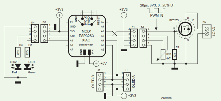
The schematic diagram is shown in Figure 1. The choice of the IRF3205 MOSFET was deliberate. With a 55-V threshold and a 110-A current rating, it’s able to handle tough tests without hesitation. With a heat sink, it can consistently dissipate heat, despite the stringent demands of continuous power dissipation.
Central to the design is the small XIAO ESP32S3 microcontroller breakout board from Seeed. To simplify prototyping, I used a very compact extension board for this XIAO module. (Meanwhile, we developed our own Elektor XIAO extension board, see .) At such an extension board, the GPIOs at the pin headers of the XIAO board are wired to Grove connectors, which always feature a pin for GND, a pin for 3.3 V, and two input/output/bus pins. You can see these connectors in the circuit diagram as K2, K1, J1 and J2, the latter two one are dedicated for I2C.
K2/K4 connect with each other to control LED1 and LED2, which are used to indicate the operational status and provide visual feedback for the load condition. K1/K3 are utilized with a PWM output pin switching the MOSFET, and an analog input pin sensing the potentiometer value. With that potentiometer it is possible to let the firmware adjust the PWM duty cycle, delivering granular modulation of the load.
R1 is a pull-down resistor between the gate and source of the MOSFET, ensuring the gate is properly discharged when the PWM signal is off, preventing unintended switching.
The schematic for the digital load includes options for future enhancements, such as an OLED display and a current sensor. However, to maintain simplicity in the initial design, a potentiometer is utilized for straightforward manual control of the load settings. This approach allows for basic operation while keeping the door open for more complex functionality to be integrated later.
Test Setup
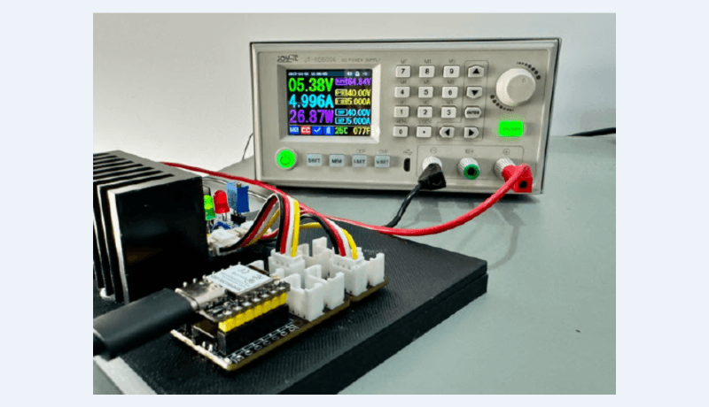
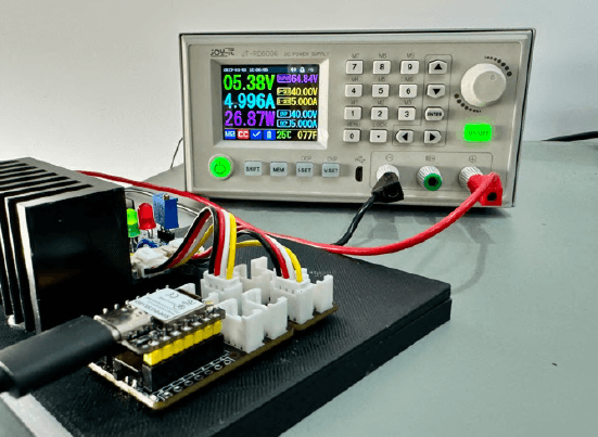
I made a test with the right part of the circuit, inserting a PWM signal coming from a wave generator at pin 4 of K3. A digital power supply was hooked up with the K5 connector, with the source of the T1 connected to the negative terminal and the drain of T1 connected to the positive terminal of the power source . After that PWM wave was applied to the gate with a period of 20 µs with 3.3 Vpp amplitude and 3% to 50% duty cycle, and I measured the current going through the MOSFET with the digital power supply and a multimeter.
On about 21.3% duty cycle, the electronic load was close to 4.9 A, as seen in Figure 2. Further increasing the duty cycle can increase the current flow, but this also leads to high case temperature, reaching 70°C, without any active cooling, so it’s recommended that we use a bigger a heat sink with active cooling. Using two or more MOSFETs in parallel can also to increase the current limit and reduce high temperatures.
Software
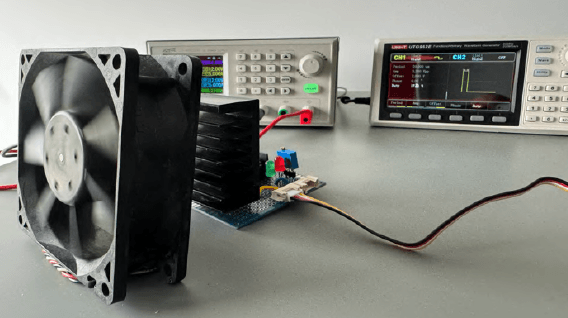
The firmware was built on Arduino IDE, designed to control a PWM signal using an ESP32, with a potentiometer to adjust the duty cycle and LEDs to indicate the system’s state (Listing 1 - the code is posted at the bottom of the article). It begins with defining the necessary pins for the potentiometer, PWM output, and LEDs, as well as setting PWM parameters, including a 50 kHz frequency, 8-bit resolution, and a maximum PWM value of 255. In the setup function, the Serial interface is initialized for debugging, and the LED pins are configured as outputs. The PWM is set up on the specified pin with the defined frequency and resolution. Initially, the code reads the potentiometer’s position and checks if it exceeds the minimum voltage threshold. If so, the red LED lights up, and the system waits for the user to adjust the potentiometer to its minimum value.
In the main loop, the code continuously reads the potentiometer value, converts it to a voltage, and maps this voltage to a PWM duty cycle ranging from 0 to 50% of the maximum PWM value. This duty cycle is then written to the PWM pin. The green LED is turned on to indicate normal operation. Additionally, the code prints debug information, including the duty cycle percentage and potentiometer voltage, to the Serial Monitor. In Figure 3 you can see the project in action, adjusting the load based on the potentiometer setting.
For those interested in replicating or customizing this project, all the code and schematics are shared on GitHub. This provides you with all the necessary resources to get started and adapt the electronic load to your specific requirements. As we are using an ESP32, it unlocks the ability to control the digital load wirelessly, by running a web server on the ESP32 to control the digital load via web interface over Wi-Fi, or even through the internet remotely. Possibilities are endless!
Editor's note: This article (240203-01) appears in the Elektor Circuit Special 2024.
Listing 1: Basic firmware.
#include <Arduino.h>
// Pin definitions
#define POT_PIN 3
#define PWM_PIN 2
#define RED_LED_PIN 9
#define GREEN_LED_PIN 8
// PWM parameters
const long pwmFrequency = 50000; // 50 kHz to achieve a 20 us period
const uint8_t pwmResolution = 8; // 8-bit resolution for PWM
const uint8_t maxPwmValue = 255; // Maximum value for 8-bit resolution PWM
// ADC and Voltage settings
const float referenceVoltage = 3.3; // ADC reference voltage in volts
const int adcMaxValue = 4095; // Maximum ADC value for 12-bit resolution
const float minimumVoltage = 0.1; // Minimum voltage threshold to start PWM
void setup() {
// Initialize Serial for debug output
Serial.begin(9600);
// Set up LED pins
pinMode(RED_LED_PIN, OUTPUT);
pinMode(GREEN_LED_PIN, OUTPUT);
// Initialize PWM on pin
ledcSetup(0, pwmFrequency, pwmResolution);
ledcAttachPin(PWM_PIN, 0);
// Check initial position of the potentiometer
float initialVoltage = (analogRead(POT_PIN) * referenceVoltage) / adcMaxValue;
if (initialVoltage > minimumVoltage) {
digitalWrite(RED_LED_PIN, HIGH); // Turn on red LED
digitalWrite(GREEN_LED_PIN, LOW); // Make sure green LED is off
while ((analogRead(POT_PIN) * referenceVoltage / adcMaxValue) > minimumVoltage) {
// Wait for the user to adjust the potentiometer to minimum
delay(100); // Delay to avoid excessive reading
Serial.println("Adjust potentiometer to minimum to start.");
Serial.println((analogRead(POT_PIN) * referenceVoltage / adcMaxValue));
}
}
// Potentiometer is at minimum value, proceed with normal operation
digitalWrite(RED_LED_PIN, LOW);
digitalWrite(GREEN_LED_PIN, HIGH);
}
void loop() {
// Read the potentiometer value and convert to voltage
float potVoltage = (analogRead(POT_PIN) * referenceVoltage) / adcMaxValue;
// Calculate the PWM duty cycle (0 - 50% of maximum PWM value)
int pwmDutyCycle = map(potVoltage * 1000, 0, referenceVoltage * 1000, 0, 128);
// Set the PWM duty cycle
ledcWrite(0, pwmDutyCycle);
digitalWrite(GREEN_LED_PIN, HIGH);
// Debug output to Serial Monitor
Serial.print("Duty Cycle: ");
Serial.print((float)pwmDutyCycle / maxPwmValue * 100);
Serial.println("%");
Serial.print("Potentiometer Voltage: ");
Serial.print(potVoltage);
Serial.println(" V");
}


Discussion (1 comment)