
Perpetual Steel Ball Track
As perpetual as the laws of physics of this universe allow
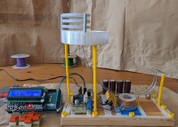
A Steel Ball spirals in a bowl, falls through a hole onto a course, mystically accelerates and is thrown back into the bowl and it starts all over again, a sensor and an electromagnet and some electronics make it possible.
The Idea for building this device came to me while looking at a commercially available version. It was a long journey with much trial and error before the replica finally worked. The track had to be bent from steel wire, parts for the frame, collecting bowl, and supports had to be made with the 3D printer, the electromagnet had to be wound, and the electronics and software had to be developed.
For more information see
https://github.com/qrti/perpSteel
It All Started with a YouTube video discussing a similar apparatus. From the detailed footage and the assumption that a 1/2 inch steel ball was used, the approximate size and path of the track could be estimated. Galvanized iron wire of the appropriate diameter was quickly procured, and the know-how on how to straighten coiled wire was also found in a YouTube video. After watching another video, it became clear how to bend a track for steel balls and elegantly connect the two rails. In practice, however, this wasn't always as simple as shown in the videos; what seems effortlessly easy often requires a lot of practice and skill.
The curvature of the track was modeled in Blender based on the video, estimation, and intuition. From this, two templates were created on the 3D printer, one for the inside and one for the outside of the curve. This made it easier to gradually shape the wire—bend, hold in place, bend, hold in place. And then do it all over again as identically as possible for the second rail.
The semicircular wire pieces used in the video to hold the rails together were quickly made, but how to maintain consistent spacing of the curved rails when soldering? Here too, Blender and the 3D printer helped; small, fixable spacers solved the problem. The centerpiece, the 'iron wire track,' was now finished. The drop height, position of the catch bowl, and the magnet at the lowest point were thus determined.
Using the acquired measurements, a provisional base frame, a catch bowl, and supports for the track and bowl were also created with Blender and the 3D printer. The supports were glued to movable frame rails and then temporarily fixed in the base frame at suitable locations, and after aligning with the bowl and track, they were permanently glued in place.
The position of the electromagnet was clear—at the lowest point of the track curve. This also determined the position of the inductive sensor, just before the magnet. It was also clear that a significant amount of energy needed to be supplied to give the steel ball enough impulse via the electromagnet so that it would safely land in the bowl. The efficiency of such devices is low; it is reportedly only around 3%. The mechanical impulse transfer from the magnet to the ball is downright miserable due to unfavorable angles; a lot of energy is also "lost" in track friction and the resulting strong rotation of the ball. You can sometimes observe the ball's rotation in the "crazy dance" it performs after hitting the bowl, before it then more or less leisurely spirals into the center of the bowl.
Numerous attempts with commercially available electromagnets failed—too little core, too high resistance in the winding, too large in size. Even a self-wound version with 1 mm enameled copper wire at 30 mm diameter and a 1 cm iron core brought no improvement; the ball would lazily plop back onto the track after only a short flight. A much more promising attempt was only achieved with 0.8 mm wire on a 2 cm core, but it still didn't quite work—this was due to another crucial component: the capacitors.
Initially, supercapacitors were used as energy storage, but it quickly became clear that their low nominal voltage of only 3 V, despite high currents, did not drive enough energy through the electromagnet's winding. Their relatives, four low-ESR capacitors with a nominal voltage of 35 V connected in parallel, then brought the breakthrough—the steel ball easily flew back into the catch bowl and sometimes even overshot the target.
To switch the high currents, an inexpensive 55 V 75 A N-MOSFET with 8 milliohm source-drain resistance proved effective. The delay from when the steel ball hits the sensor to when the electromagnet is triggered, as well as the duration of the magnetic pulse, is controlled by an Arduino Mega 2560. The timing can be conveniently adjusted via its LCD keypad shield.
To increase the stability of the setup, the device was bolted to a suitable wooden board on the base frame after the experimentation phase was completed.
Discussion (2 comments)