Article
I2C Interface for Lego RCX 'Brick'
makes unprecedented extensions possible!
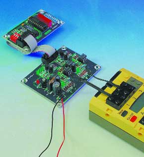
It has, by now, become well known that the Lego RCX-module is eminently suitable for experimenting with such things as robotics. But once the designs grow beyond simple experimentation it quickly becomes obvious that the number of inputs and outputs that this control module provides, are rather insufficient. That’s why Elektor Electronics presents the I2Cinterface for this Lego brick. An entirely new world is opened up: in principle, no fewer than 128 I2C-devices may be connected to the bus!The RCX, the ‘intelligent’ component of the Lego Robotics Invention System, which forms part of the Lego Mindstorms program, is eminently suitable to serve a as the basis of various automation applications. Apart from the programming that is still required, it is very easy to assemble, for example, a small robot together with ‘normal’ Lego parts. However powerful or modular the design of the RCX-module may be, when more things have to be controlled or measured than are possible with the three inputs and the three outputs, you’re out of luck…
Materials
Gerber file
CAM/CAD data for the PCB referred to in this article is available as a Gerber file. Elektor GREEN and GOLD members can exclusively download these files for free as part of their membership. Gerber files allow a PCB to be produced on an appropriate device available locally, or through an online PCB manufacturing service.
Elektor recommends the Elektor PCB Service service from its business partner Eurocircuits or AISLER as the best services for its own prototypes and volume production.
The use of our Gerber files is provided under a modified Creative Commons license. Creative Commons offers authors, scientists, educators and other creatives the freedom to handle their copyright in a more free way without losing their ownership.
PCB
Component list
(interface board)
Resistors:
R1,R6,R7,R12,R13 = 1kOhm
R2,R8 =3kOhm 3
R3,R5,R9,R11 = 100Ohm
R4,R10 = 4kOhm 7
Capacitors:
C1,C3 = 22µF 16V radial
C2,C4 = 1µF 16V radial
C5 = 220µF 25V radial
C6 = 100nF
C7 = 1000µF 16V radial
Semiconductors:
D1, D14 = zender diode 4.7V 400mW
D2-D13,D15-D26 = 1N4148
D27 = low-current LED
T1-T4 = BC547
IC1-IC4 =CNY17-2
IC5 = 7805
Miscellaneous:
K1,K2,K3 = 6 PCB solder pins
K4 = 10-way boxheader
Disk, project software, order code 010089-11 or free download
(test board)
Resistors:
R1-R8 = 560Ohm
R9,R10,R11 = 10kOhm
Capacitors:
C1,C2 = 100nF
C3 = 10µF 16V radial
Semiconductors:
D1-D8 = rectangular LED
IC1 = PCF8574
IC2 = 74HCT245
Miscellaneous:
K1 = 10-way boxheader
S1 = 3-way DIP switch (4-way will also fit)
Resistors:
R1,R6,R7,R12,R13 = 1kOhm
R2,R8 =3kOhm 3
R3,R5,R9,R11 = 100Ohm
R4,R10 = 4kOhm 7
Capacitors:
C1,C3 = 22µF 16V radial
C2,C4 = 1µF 16V radial
C5 = 220µF 25V radial
C6 = 100nF
C7 = 1000µF 16V radial
Semiconductors:
D1, D14 = zender diode 4.7V 400mW
D2-D13,D15-D26 = 1N4148
D27 = low-current LED
T1-T4 = BC547
IC1-IC4 =CNY17-2
IC5 = 7805
Miscellaneous:
K1,K2,K3 = 6 PCB solder pins
K4 = 10-way boxheader
Disk, project software, order code 010089-11 or free download
(test board)
Resistors:
R1-R8 = 560Ohm
R9,R10,R11 = 10kOhm
Capacitors:
C1,C2 = 100nF
C3 = 10µF 16V radial
Semiconductors:
D1-D8 = rectangular LED
IC1 = PCF8574
IC2 = 74HCT245
Miscellaneous:
K1 = 10-way boxheader
S1 = 3-way DIP switch (4-way will also fit)
Discussion (0 comments)