Article
Poor Man's 1-GHz Active Probe
DIY saves a pretty penny

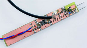
When it is required to make a measurement at a node of an RF circuit, connecting to the circuit using a normal oscilloscope probe, even on the x10 setting can change the behaviour of the circuit. For those difficult cases, you need a special probe like the one described here.Any probe presents extra impedance for the circuit to drive, usually consisting of some resistance and stray capacitance, resulting in reduction in gain, or in extreme cases, causing instability. The loading effect of the resistance and stray capacitance can be largely removed by using an active probe. The major manufacturers in the oscilloscope market all offer suitable models (see also ‘Scope for Scopes’ elsewhere in this issue), but costing over a £1000 they are too expensive for amateur use. This article describes a probe that can be constructed at home, for very little money and has useful performance.
Materials
Gerber file
CAM/CAD data for the PCB referred to in this article is available as a Gerber file. Elektor GREEN and GOLD members can exclusively download these files for free as part of their membership. Gerber files allow a PCB to be produced on an appropriate device available locally, or through an online PCB manufacturing service.
Elektor recommends the Elektor PCB Service service from its business partner Eurocircuits or AISLER as the best services for its own prototypes and volume production.
The use of our Gerber files is provided under a modified Creative Commons license. Creative Commons offers authors, scientists, educators and other creatives the freedom to handle their copyright in a more free way without losing their ownership.
PCB
Component list
All resistors and capacitors: SMD, ‘0805’ case
Resistors:
R1 = 10MOhm
R2 = 4kOhm 7
R3 = 6kOhm 8
R4 = 47Ohm
Capacitors:
C1 = PCB capacitor
C2,C4 = 1nF
C3 = 100nF
C5,C6 = 470nF
Semiconductors:
D1 = 1A diode, SMD
T1 = BF998 in SOT143 case (see Table 2)
IC1 = 78L05 in SO-8 case
Resistors:
R1 = 10MOhm
R2 = 4kOhm 7
R3 = 6kOhm 8
R4 = 47Ohm
Capacitors:
C1 = PCB capacitor
C2,C4 = 1nF
C3 = 100nF
C5,C6 = 470nF
Semiconductors:
D1 = 1A diode, SMD
T1 = BF998 in SOT143 case (see Table 2)
IC1 = 78L05 in SO-8 case


Discussion (0 comments)